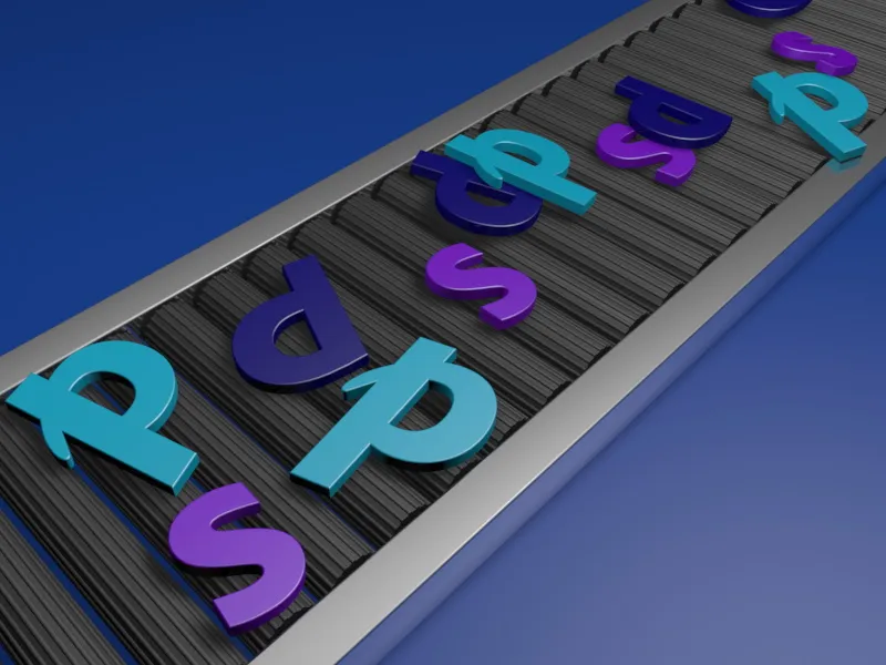
In the working file "PSD_C4D_R12_Dyn_Motor_Fliessband_Start.c4d" you will find the basic structure of the scene so that we can get straight to work with MoGraph and Dynamics. In addition to the floor and the conveyor belt frame, this also includes the first roller for the later conveyor belt.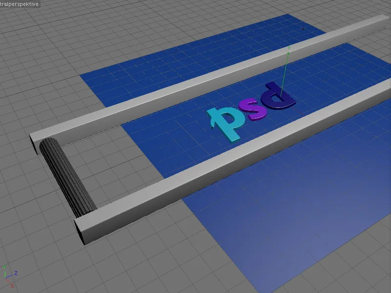
In my example, the three letters p, s and d serve as transport material for the conveyor belt. Of course, you can use any other object you like - as long as it fits on the conveyor belt ...
You will also find a pre-installed camera in the scene. While we are working on the scene, this camera is deactivated (black viewfinder icon in the Object Manager) and also made invisible so that it does not interfere with the editor.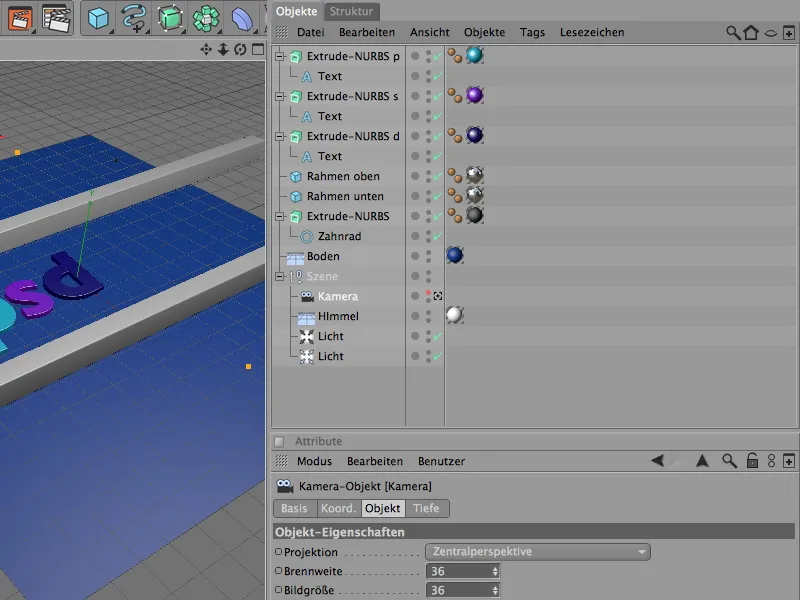
I generated the letters using simple text spline objects, which are located in an Extrude NURBS object. If you want other letters or symbols, you can easily change this via the settings dialog of the text object or by using a different spline object.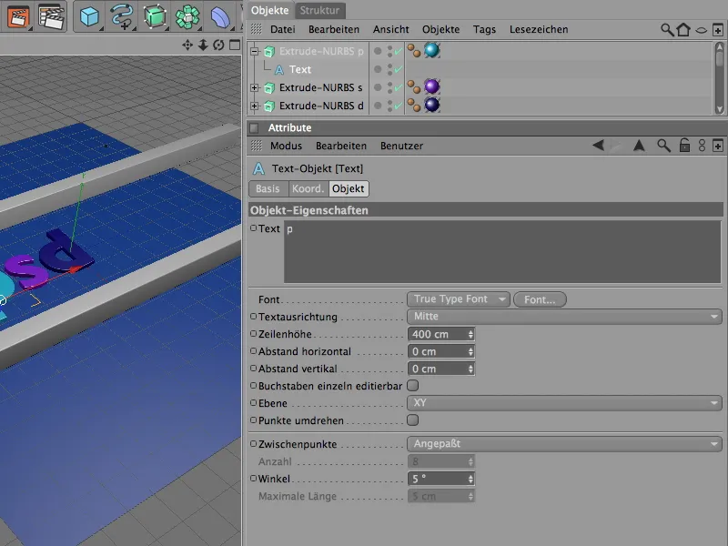
In the settings dialog of the Extrude NURBS generator, the cover areapage ensures that there is also a slight rounding next to the cover areas.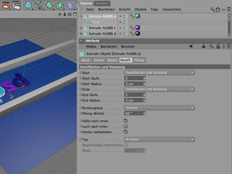
There are two cube objects in the scene for framing the conveyor belt. If you need a longer conveyor belt, simply increase the Z-size of the cube objects accordingly.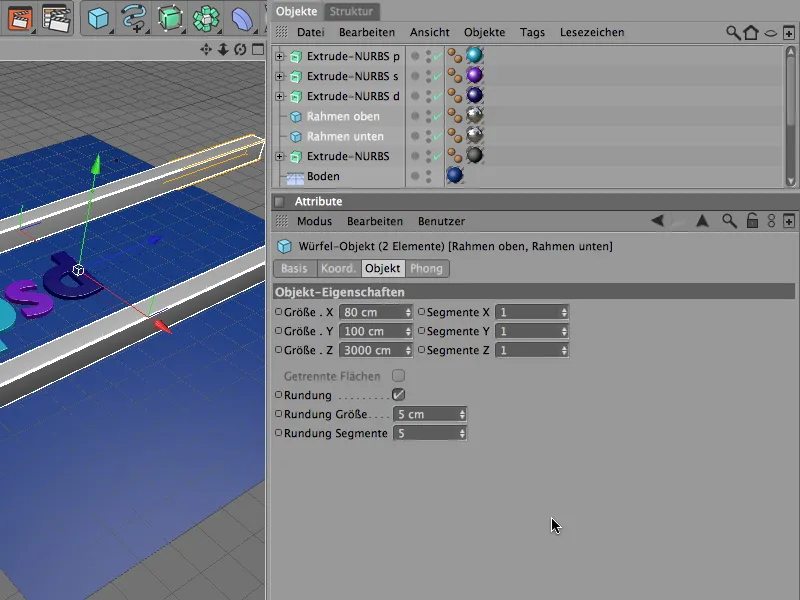
For the conveyor rollers of the conveyor belt, we only need a single roller as a starting point, which we can later simply clone in the required number using MoGraph. To ensure that the conveyor rollers also have a good grip, a gear spline with a correspondingly small radius difference and high chamfer is used as the contour for the Extrude NURBS object.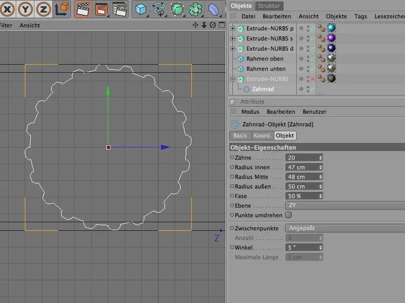
With an offset of 600 cm in the X direction, the Extrude NURBS object generates a suitable conveyor roller for the conveyor belt. Due to the filigree gear contour, the rounding radius is correspondingly small.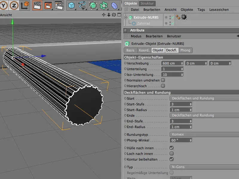
Drive of the conveyor roller with motor and connector
The work in Dynamics should now finally begin with the conveyor roller. For a better overview, we temporarily switch the three letters to invisible via the object manager.
In order for the modeled conveyor roller to be accepted by Dynamics, we have to integrate it as a Dynamics body. As it is actively involved in the action, we assign it a Dynamics Body tag as a Rigid Body via the Simulation>Dynamics menu.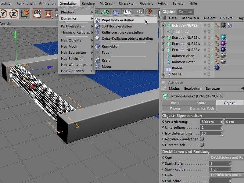
In the settings dialog of the Dynamics Body tag, we also adjust the dynamic parameters for the conveyor roller. As the rollers are to be moved without delay by the subsequent drive, we start the triggering immediately.
The conveyor roller is practically cylindrical and poses no problem for Dynamics' automatic collision shape detection. The elasticity value of 50% ensures that the impacting clones do not spin back too high, while the friction of 100% keeps the clones non-slip on the conveyor rollers.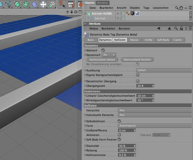
The Extrude NURBS object of the conveyor roller is only part of the functional unit that we will later clone into a conveyor belt. There is also a connector and a motor to ensure that the roller drive works as desired.
We combine these three components in a null object, which also provides us with its axis as a reference point. So we get it from the Objects menu into our scene.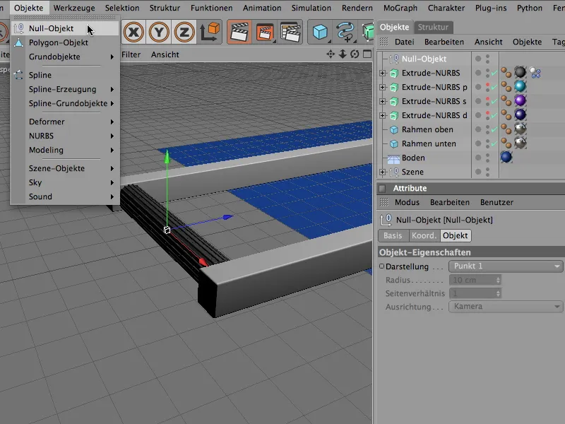
The position of the zero object in the Y and Z directions is at the height of the roller center point; at the same time, it sits directly on the X axis. The quickest way to teach these values to the null object is via the Coordinate Manager or the Attribute Manager.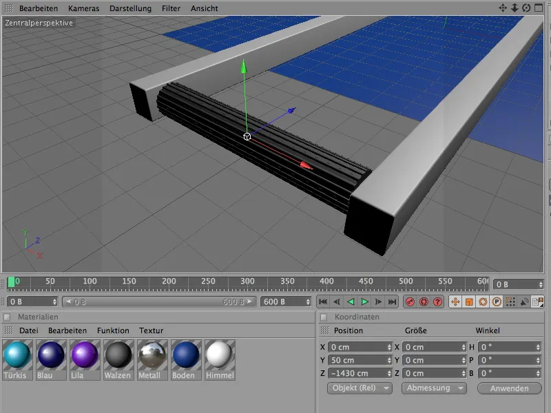
After we have placed the Extrude NURBS object of the conveyor roller in the null object for the functional unit via the Object Manager, we create a connector via the Simulation>Dynamics menu. It should be used to hold the roller in position and only allow rotation along its X axis.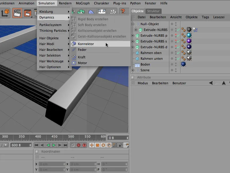
As the connector also belongs to our functional unit, we also place it as a sub-object in the null object with the conveyor roller. The exact positioning of the connector is now easy for us, because as it is a sub-object of the null object, we only need to set all position values to 0 in order to align the position with the null object.
To ensure that the connector works in the correct direction, we set its heading angle to -90° using the attribute or coordinate manager. On the display page of the settings dialog, we set the size of the connector to 50 cm so that the connector fits better in our conveyor roller.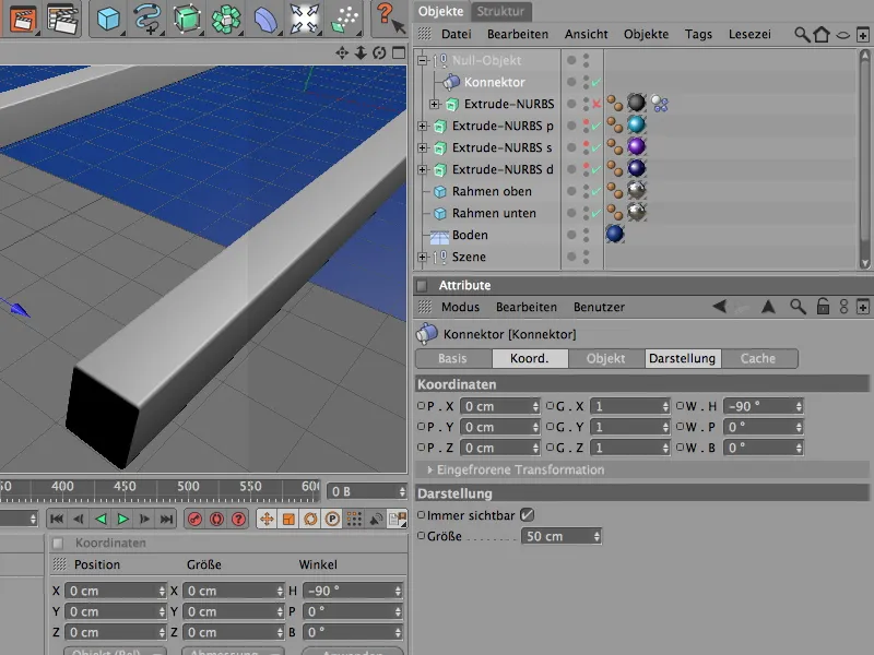
CINEMA 4D uses the hinge as the default type for the connector - so we don't need to change this at all. On the object page of the settings dialog, we now create the fixed connection between the null object and the conveyor roller using the two object fields A and B. To do this, we drag the corresponding objects from the Object Manager into the fields provided for this purpose in the connector settings dialog.
The X-axis serves as the reference axis for the zero object and the Z-axis for the conveyor roller due to the alignment of the Extrude NURBS object.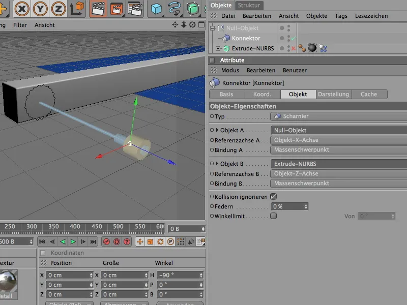
As the last element of the function group, we integrate the actual drive that makes the conveyor roller rotate. To do this, we get a motor object from the Simulation>Dynamics menu.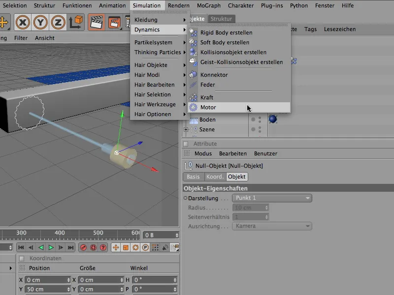
The motor object is also added to the group of conveyor roller elements. Here too, we adjust the position by simply setting it to coordinate 0 and rotate the drive direction of the motor in the correct direction using the heading angle of 90°. The direction of rotation of the motor is determined by the yellow arrow, while the blue arrow symbolizes the counterforce.
The Angle function is already set correctly for the motor type, and its drive force is transmitted to the Extrude NURBS object of the conveyor roller via the Object A field.
We use the two parameters Angle target speed and Torque to regulate the drive and, as a result, the speed of the conveyor roller. The torque is the force that is available to reach the specified target speed.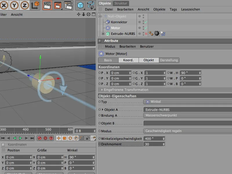
This completes the individual conveyor roller. By clicking on the play button, the roller can be tested for proper function. This complete unit should now be duplicated by cloning the entire conveyor roller area.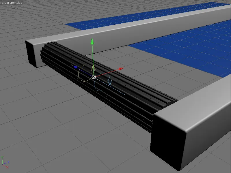
Creating clones for the conveyor roller belt
When it comes to clones, MoGraph can't be far behind. Instead of laboriously creating many copies of the first conveyor roller, we simply let the clone object do this work fully automatically. We can find it in the MoGraph menu.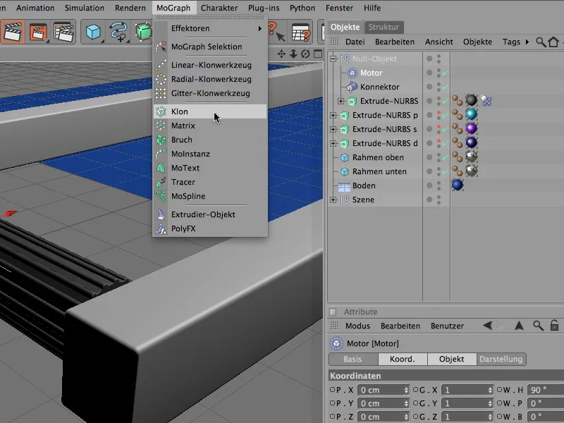
In the settings dialog of the clone object, we first take care of the correct positioning of the clone generator. To do this, we simply enter the known position data of the first conveyor roller on the coordinates page.
On the object side, we now move on to the actual creation of the clones. Here we need the linear creation of duplicates. A clone number of 27, each placed 110 cm apart per step, will fill our conveyor belt frame with a sufficient number of conveyor rollers.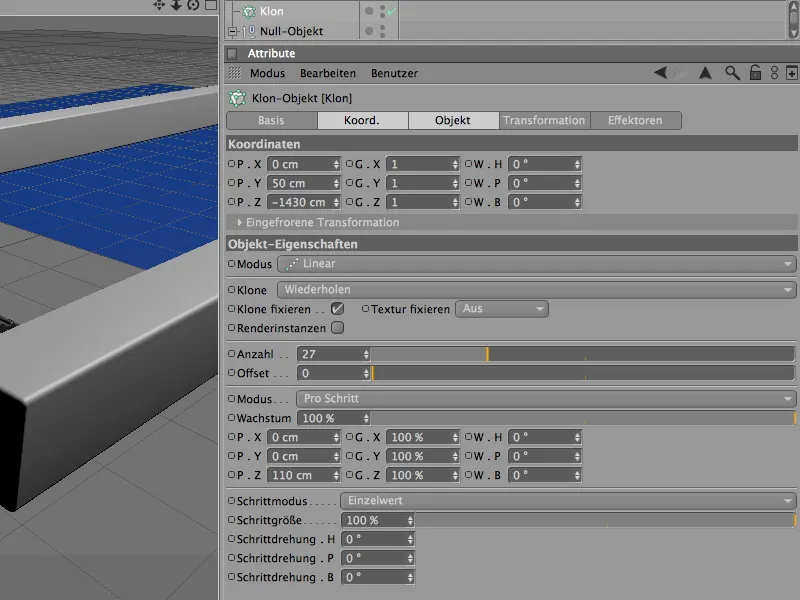
Now that the clone object knows all the required parameters, we create the conveyor roller function group as a clone sub-object via the object manager. We have already produced the desired conveyor roller belt in full length.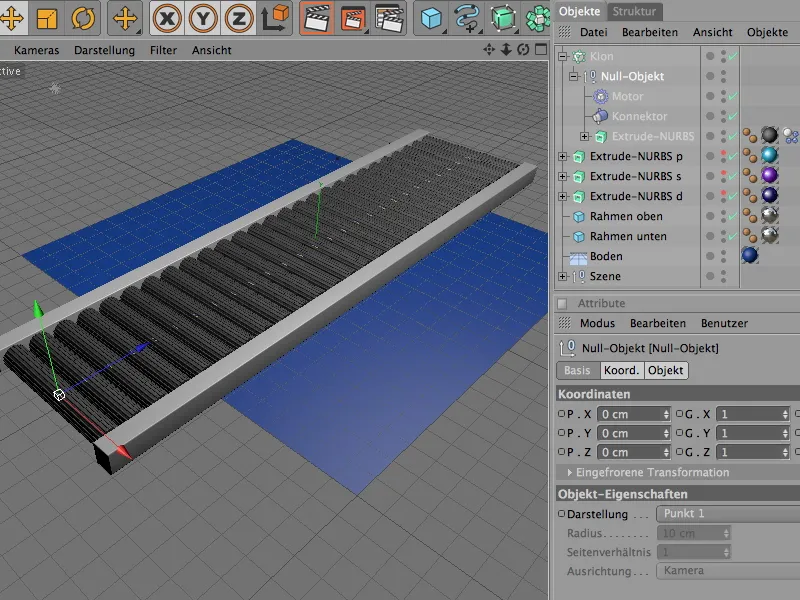
Creating the other Dynamics elements
Each of the cloned conveyor rollers is already integrated into our Dynamics simulation. Now the floor, the frame elements and the letters still need the appropriate Dynamics properties.
We start with the floor object, which only needs to be available as a base or for collisions. We therefore assign it a Dynamics Body tag as a collision object via the Simulation>Dynamics menu.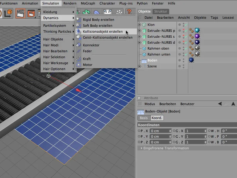
The settings dialog for the Dynamics Body tag of the floor object is reduced accordingly. On the collision page, we can use the elasticity and friction values to slow down the letters falling from the conveyor belt. In principle, the default values are completely sufficient here.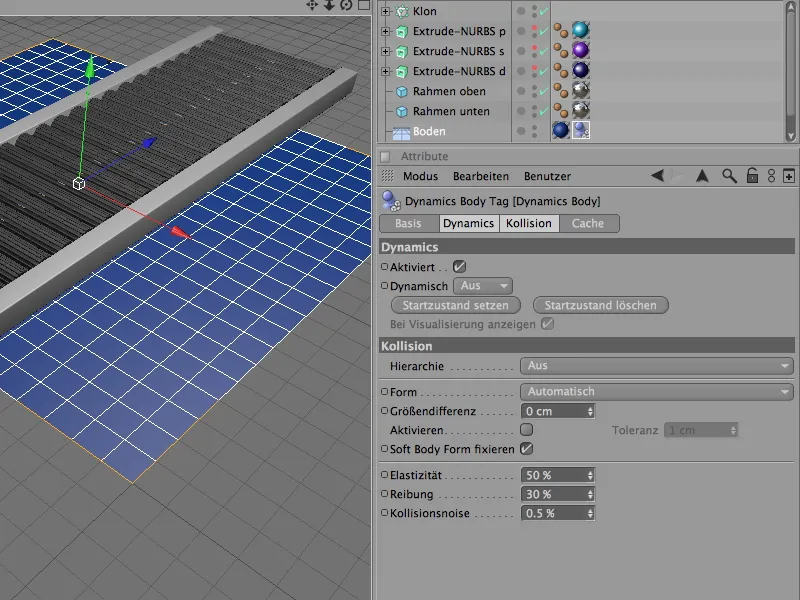
The two cube objects of the conveyor belt frame are also each assigned a Dynamics Body tag via the Create Collision Object command from the Simulation>Dynamics menu in order to act as a collision object.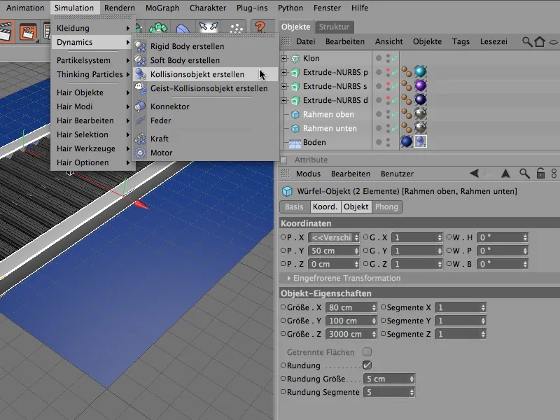
Analogous to the Dynamics Body tag of the floor object, we can directly adopt the automatically generated parameters for the collision object for the two frame objects without making any further changes.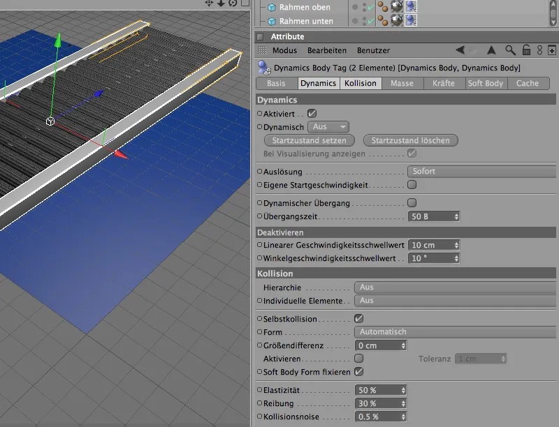
Now we are only missing the letters, which are currently still in the middle of the conveyor belt, but should actually be used as particles in an emitter. For a better overview, we deactivate the production of the conveyor roller clones via the object manager.
Before we define the three letters as particles, we assign them the necessary properties for the Dynamics simulation.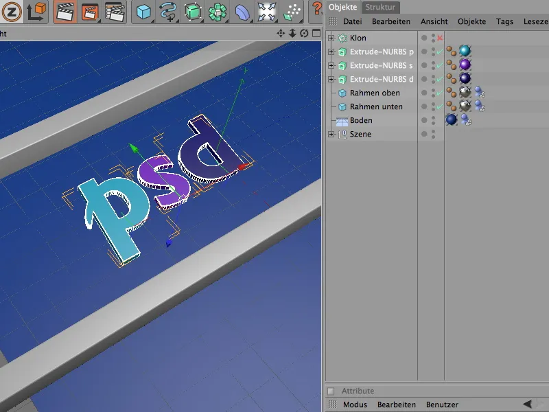
So that we can edit all three letters at the same time, we select the three Extrude NURBS objects in the Object Manager and define them as rigid bodies, i.e. as dynamic solids , using the Create rigid body command in the Simulation>Dynamics menu.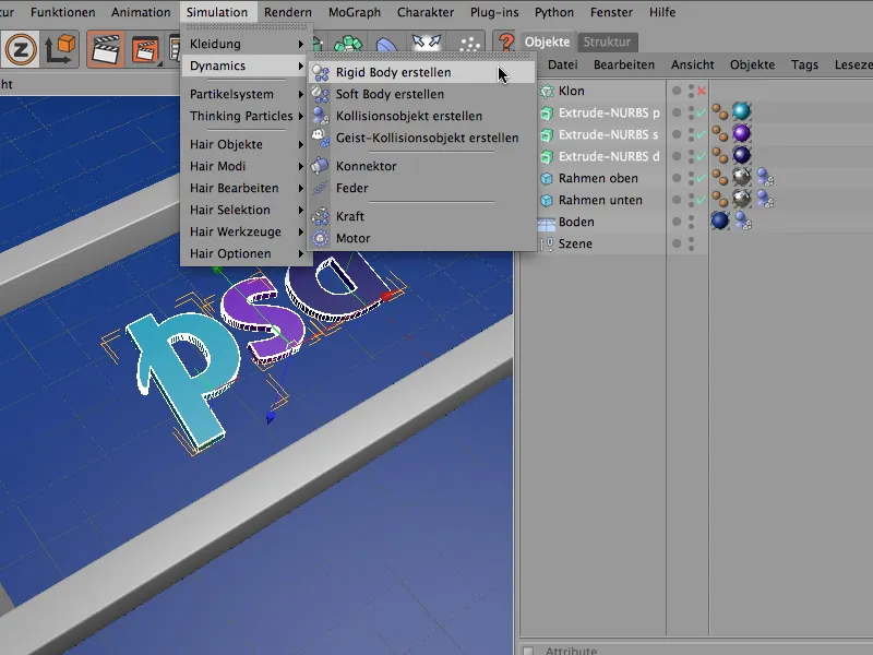
In the settings dialog of the three Dynamics Body tags of the letters, we can accept the default values for Dynamics except for the collision settings. The automatic detection of the collision shape is also sufficient here.
As usual, the elasticity value of 50% ensures a low bounce of the letters, while the increased friction of 80%, together with the high friction value of the conveyor rollers, ensures rapid braking on the conveyor belt.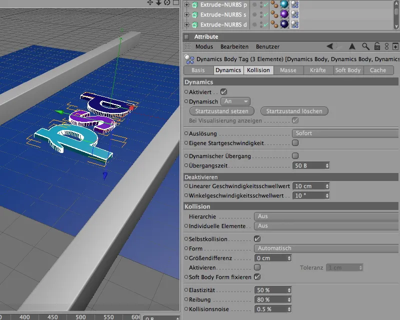
Setting up the letters as particles
Now that the letters are equipped with dynamic properties and can participate in the simulation, we integrate them as particles in a particle system. After all, we don't just want three letters on the conveyor belt - the more letters that are transported on the conveyor roller, the better.
To do this, we bring an emitter object from the range of particle system objects into the scene.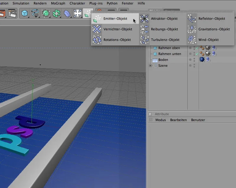
Using the settings dialog of the emitter object, we first adjust the position and size of the emitter to our requirements. As can be seen from the coordinates, the emitter is slightly below in the X direction. A little experimentation is required here - depending on where the emitter later emits the letter particles, they will fall onto the conveyor rollers.
At the same time, we turn the emitter at the pitching angle by -90° so that the particles are emitted downwards in the Y direction. We define the size of the emitter on the emitter page of the settings dialog via the X and Y length.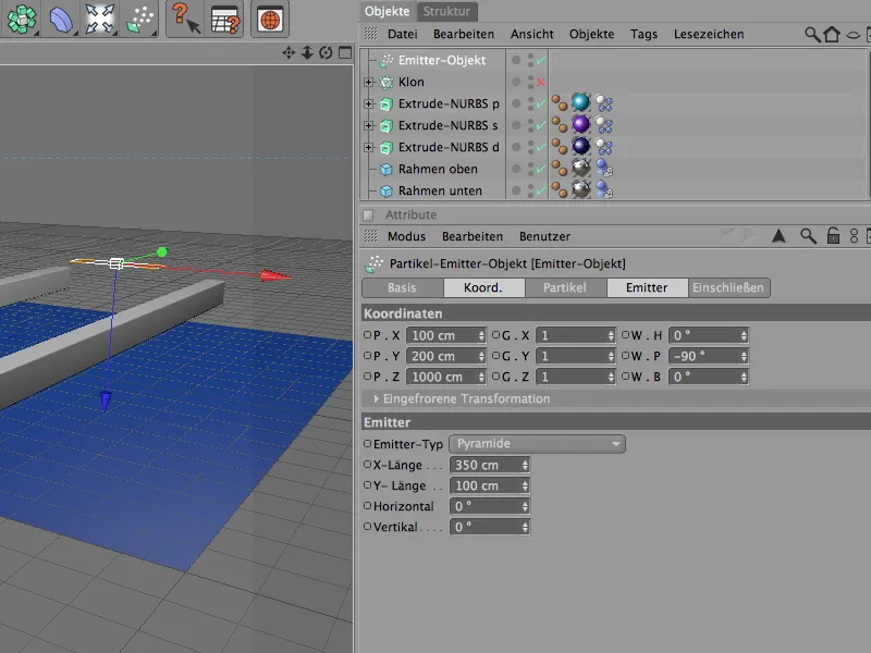
Now we come to the most important point of the emitter , the particle output, which is defined on the particle page of the emitter. Depending on the speed of the conveyor belt, too high a birth rate of particles quickly leads to a mountain of letters. My settings provide for a production of one letter per second. The particle output starts at frame 0 and ends at frame 500.
The random value can also be used to influence the particle output slightly - here again, a little experimentation is required until the optimum particle production for the conveyor belt width is found.
To ensure that all emitted particles remain visible over the entire course of the conveyor belt, we set the service life to 150 images.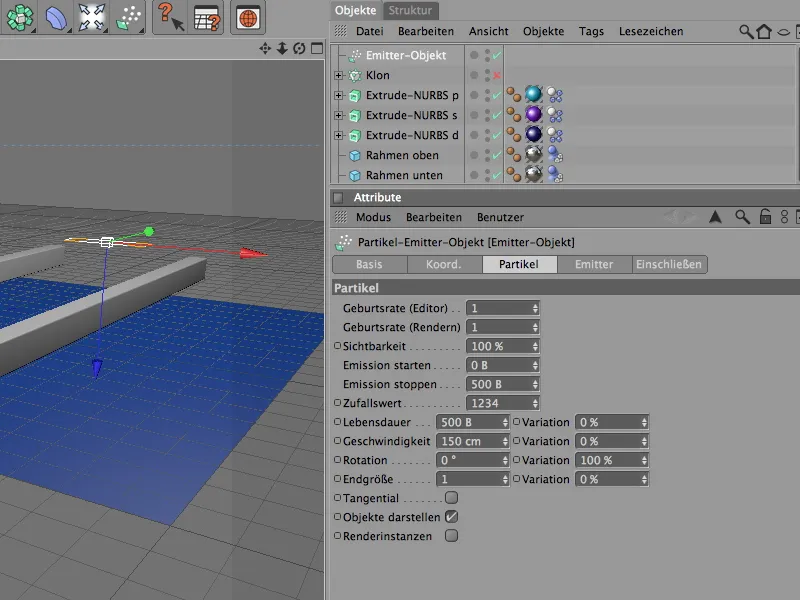
The following figure shows once again the position of the emitter above the conveyor belt. If you are using objects other than particles, you should test the particle output to ensure that the emitter hits the conveyor belt.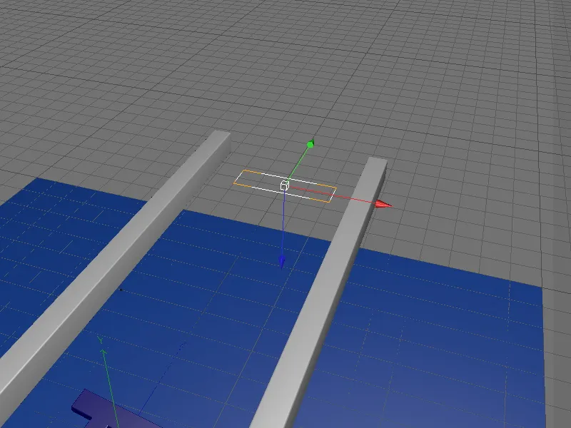
In order for the emitter to use the three letters as particles, we have to assign the three Extrude NURBS objects to it via the Object Manager.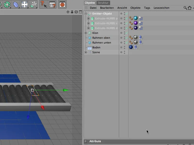
Now the three letters have also disappeared from the editor view and only reappear as particles in the scene.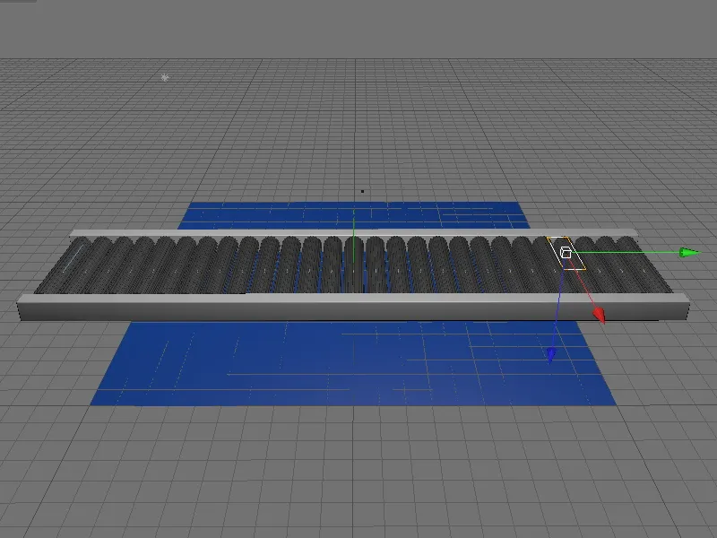
Controlling the conveyor roller speed
If you have already tested the animation, you will notice that the conveyor rollers start to rotate immediately without any start-up time. However, to ensure that the conveyor rollers only start moving fully after a short time, we simply control the speed of the rollers - or more precisely, the speed of the roller motor. Thanks to the clone object, we do not have to control 27 motors, but only the motor object contained in the function group of the conveyor roller.
As already mentioned, the torque parameter is responsible for transmitting the force; it therefore needs to be animated. To do this, we first set the current point in time to screen 0, enter the value 0 as the torque and add a key via the context menu by right-clicking on the parameter.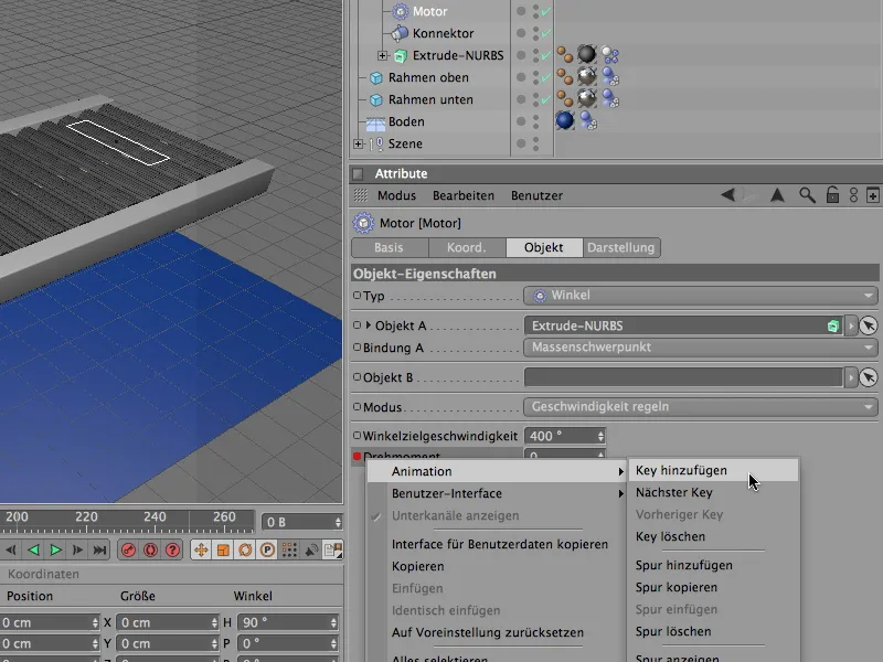
A torque of 30 should be applied from frame 25. To do this, we set the current point in time to screen 25, enter the value of 30 for the torque and add a key using the context menu with the right mouse button as before for screen 0.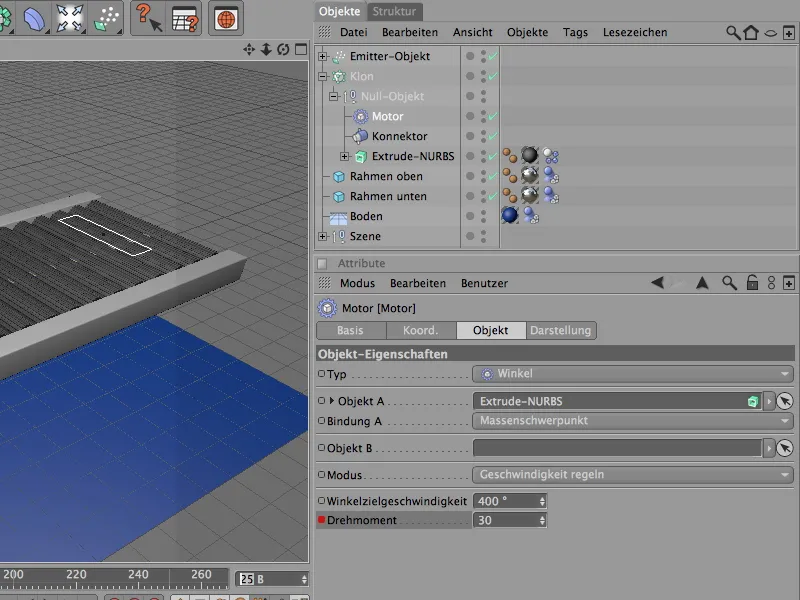
Shortly before the end of our simulation, the conveyor rollers should slow down again and finally stop. To do this, we must first write the prevailing torque during runtime in a keyframe. We set the current time to frame 565 and, as before, write a keyframe for the torque of 30 that is already present.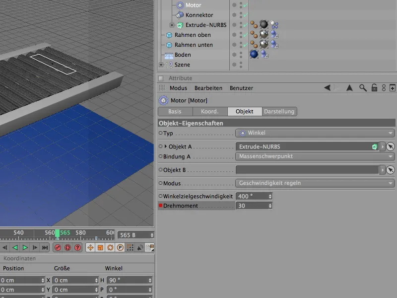
25 frames later, i.e. at frame 590, we set the torque to 0 so that the conveyor belt stops. With another keyframe, we switch off the torque completely at this point. We allow the letter particles on the conveyor belt the remaining ten frames until the end of the simulation so that they can resonate a little.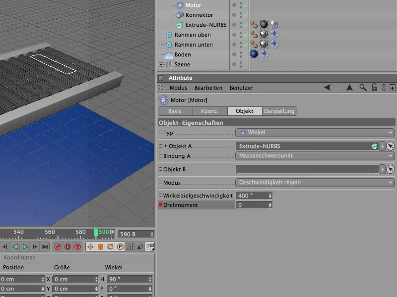
The basic settings that are important for the Dynamics simulation can be found in the document presets on the Dynamics page. In my example, we can manage with the default settings here; if you release significantly smaller or significantly more rigid body particles onto the conveyor belt, it may be necessary to reduce the scaling or increase the number of intermediate steps slightly.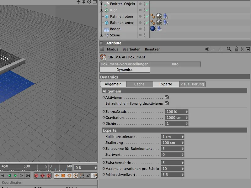
Switching to the render camera
If you are satisfied with the result of the simulation, the last step is to switch to the render camera mentioned at the beginning.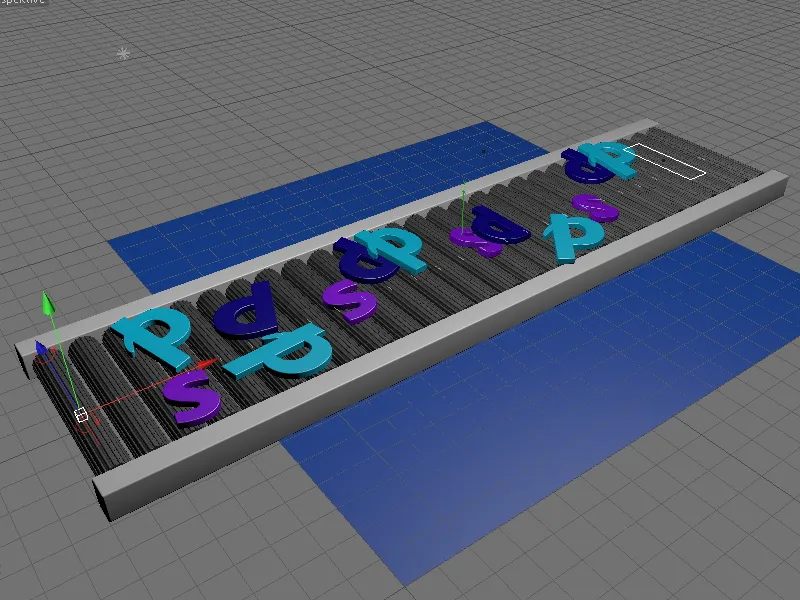
To do this, we either click on the camera's viewfinder icon in the Object Managerso that it turns white and the camera becomes active, or select the desired camera in the Editor view in the Cameras>Scene cameras menu.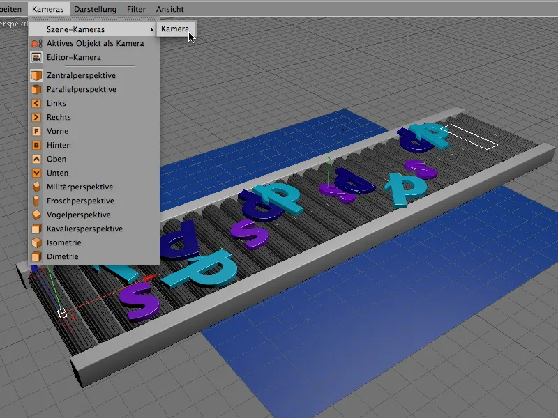
Now we have the right perspective for our dynamics simulation. Have fun experimenting!