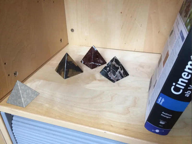
Optical distortions can prove problematic when motion tracking, for example. The smaller the focal length, the more pronounced the distorting effect towards the edges, so you have to decide whether the source material can be used directly or whether the image or film material needs to be pre-processed or the 3D elements need to be adjusted. In this tutorial, I will present both options. I have used a simple smartphone image as a starting point.
As always, you can find the Cinema 4D projects, the source image and the resulting lens profile in the working materials for this tutorial.
Preparing the lens distortion tool
In contrast to motion tracking or calibrating a camera, there is no separate object for creating a lens profile in Cinema 4D, but only the Lens Distortion tool in the Tools menu.
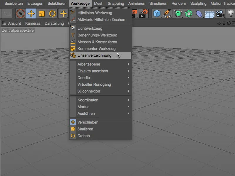
However, the tool also offers everything we need to create the lens profile in its settings dialog. On the image page, we find the basic settings for displaying the added image. This is done as usual using the button next to the image field.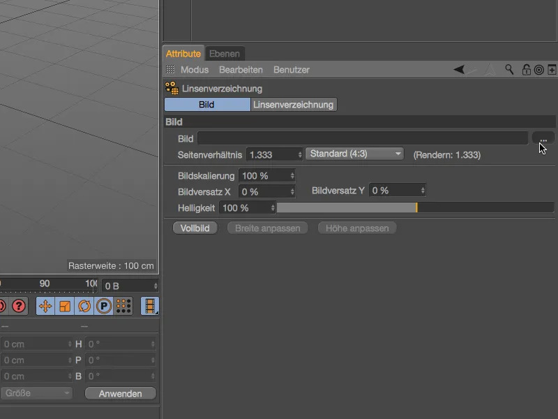
We use the selection dialog to load the image material for determining the distortion into the image fieldof the lens distortion tool.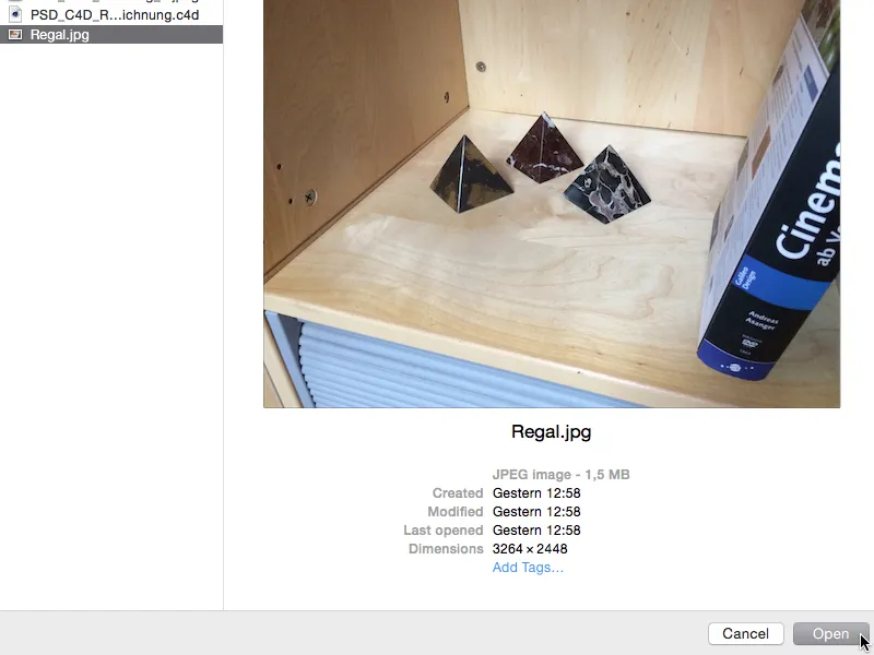
If not already set correctly, the aspect ratio adapts to the loaded image. Nevertheless, it can't hurt to check this setting after the import.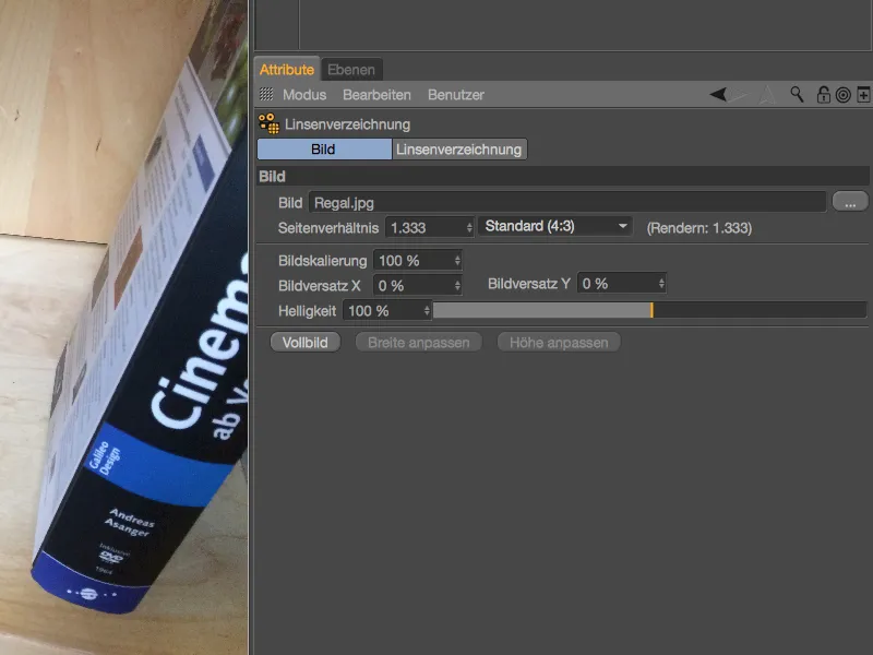
Creating the lens profile
The lens distortion pagecontains the functions for determining the lens distortion and for calculating the lens profile based on this. The distortion is determined using so-called n-point lines, which we place at suitable points in the image in the editor view. By clicking on the Add n-point line button, we create the first line for our image.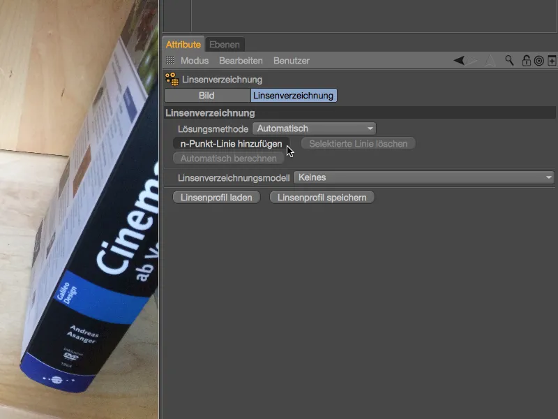
This first n-point line is now angled in the middle of our editor view, where we can edit it with the orange point handles. As the background of the loaded image is quite bright in the original, we temporarily darken the image while working with the n-point lines.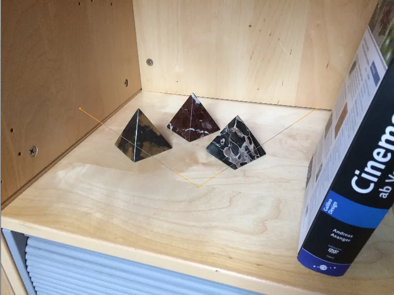
To do this, we briefly switch to the image pageof the settings dialog and reduce the brightness of the loaded image to approx. 10 % to 15 %.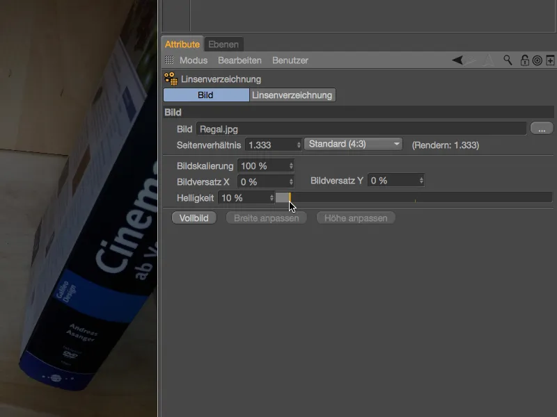
Now the n-dot lines are much easier to make out in front of the image and the relevant image elements are still clearly visible. For my first n-dot line, I chose the bottom edge of the attached shelf top. While moving the points, a magnifying glass function shows us the enlarged position of the point.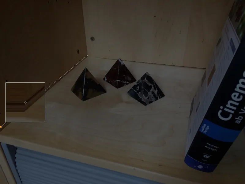
As there is no extreme distortion in my original image, the course of the edge in the image can be reproduced well with the three points of the n-point line. You can create additional points by holding down the Ctrl keyand clicking on the desired point on the line.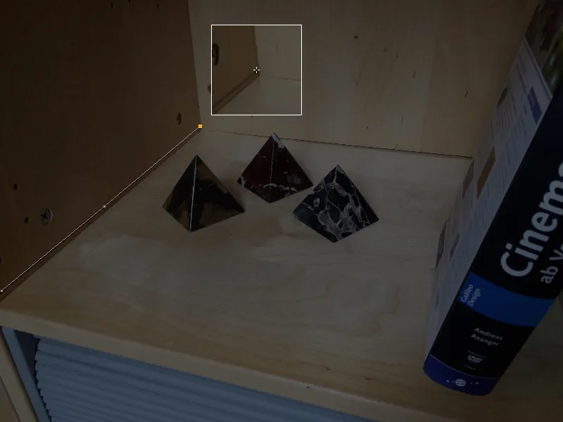
The first n-point line is placed correctly, so we can add another n-point line to the view using the Add n-point line button in the settings dialog.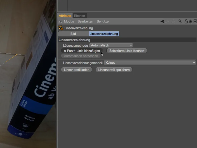
After we have used this first n-point line to recreate an edge running into the depth, our second line should cover as much of the width of the image as possible. In our case, from the bottom left rear corner ...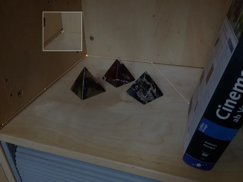
... to the point where the book covers the edge.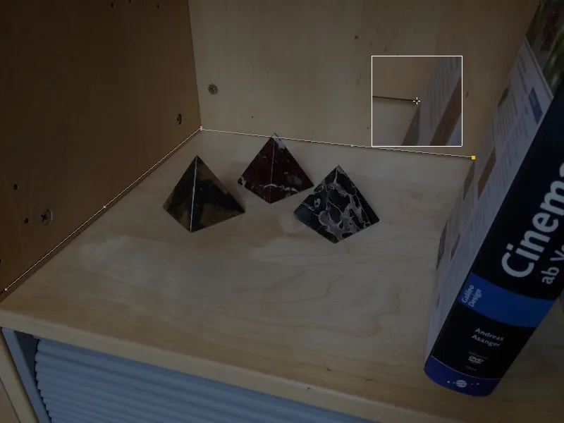
More built-in n-point lines do not always necessarily mean a better result. We limit ourselves to the edge lines in the image that are really clear and cover as many areas of the image as possible. This naturally includes the rear edge in the bookcase ...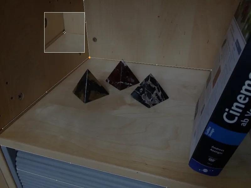
... as well as the front edges of the shelf ...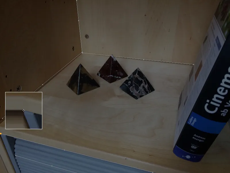
... and the slats of the roller blind, as long as they stand out well enough from the background for the n-dot lines to be drawn.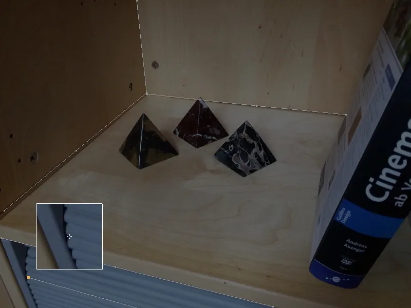
As we know that the distortions of the optical lenses increase towards the edges, it is of course important to look for suitable places for our n-dot lines there in particular.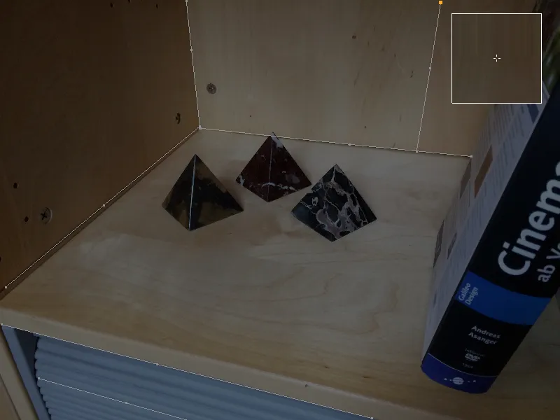
Once all the important areas of the image have been fitted with n-dot lines, we can calculate the lens profile based on this information.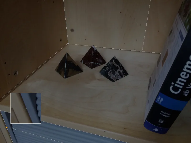
To do this, we find a menu with common lens distortion models in the settings dialog of the lens distortion tool on the lens distortion page. We select the 3DE Standard Classic model for our smartphone image.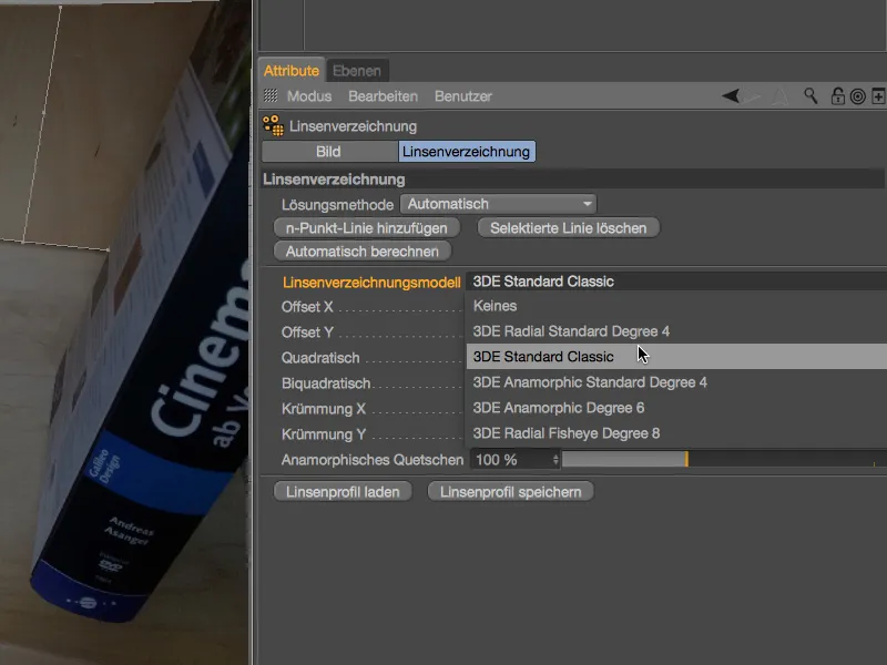
After clicking on the Calculate automatically button, the lens distortion parameters calculated from the n-point lines are entered.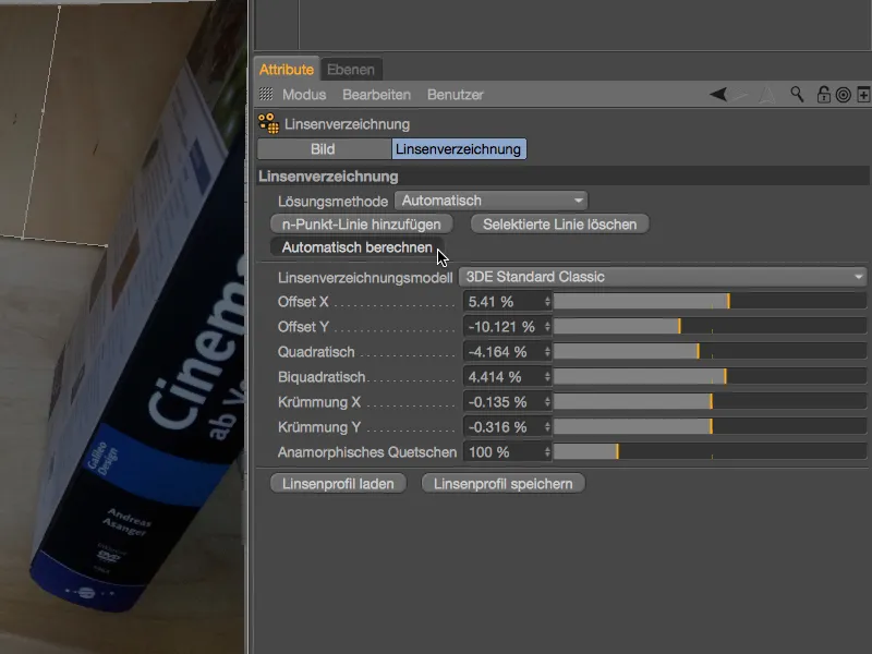
In the editor view, the distortion correction can be recognized by the slightly cushion-like shape at the edges. Also easy to see: as we have provided hardly any information for the right edge in the form of n-point lines, there is hardly any distortion or distortion correction here. For our purposes, however, the optimally covered main action area is sufficient anyway.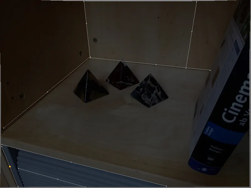
We can now use this finished lens profile to rectify the original image, as shown in the editor view. On the other hand, we can also use the lens profile to slightly distort the 3D elements in the respective areas in order to adjust them to the unchanged original image.
Before we briefly run through both variants in this tutorial, we will save the lens profile using the corresponding button.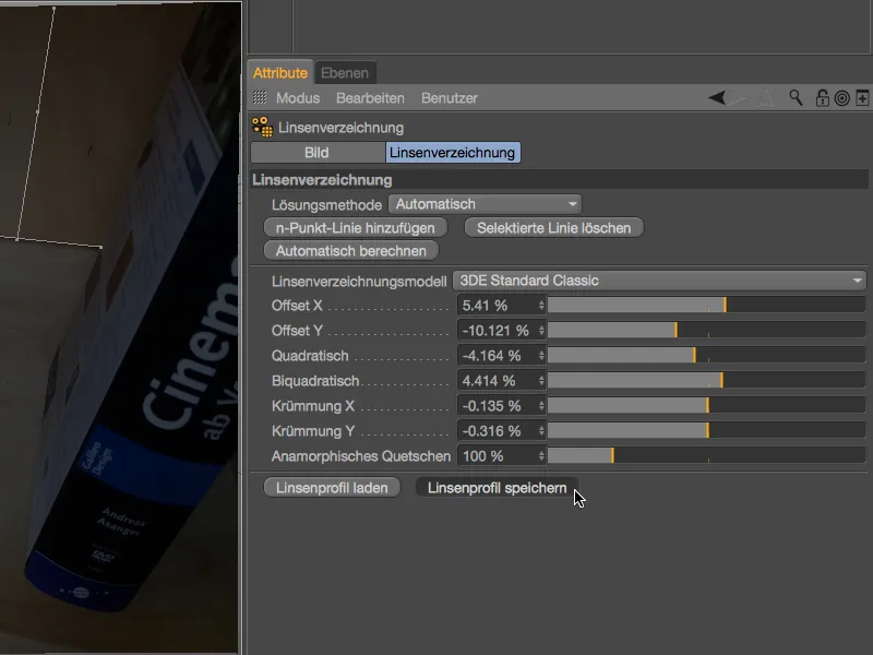
So that it is clearly recognizable that the lens profile we have just created belongs to the shelf shot, it makes sense to record this in the file name used when saving.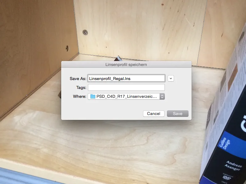
Using the lens profile to rectify a shot
Even if we still see the rectified image in the editor view: This is exclusively related to the lens distortion tool and is not yet part of our scene. To use the image as a background in a scene, we need to do this using the camera calibration in combination with a background object.
You can find a separate, detailed tutorial on the subject of camera calibration at PSD-tutorials.de, so I will limit myself here to the functions that are important for lens distortion. To calibrate the camera, we create a camera object and assign a camera calibration tagto it via the context menu using the right mouse button or via the Tags>CINEMA 4D Tags menu in the Object Manager.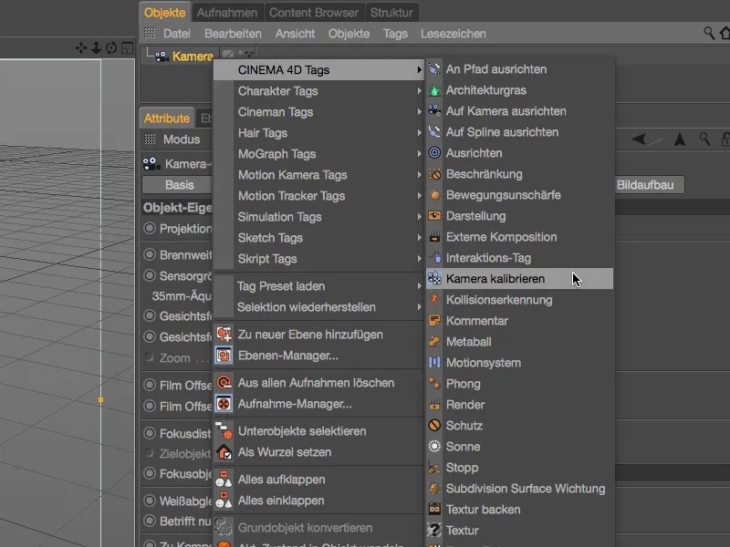
In the settings dialog of the camera calibration tag, we open the image pageand load our shelf shot into the Image field provided. In the second section of the dialog, we find the Lens profile field , whose load button on the right opens the file manager ...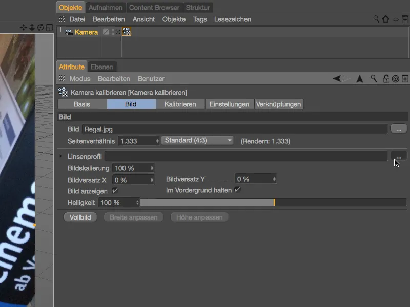
... and load the lens profile we have saved for the shelf image.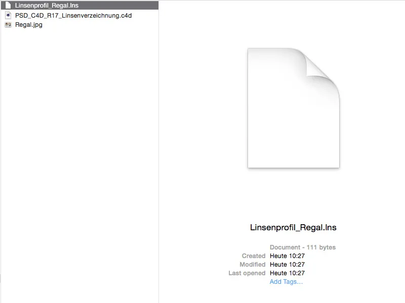
Thanks to the added lens profile, we can use the rectified image to calibrate the scene.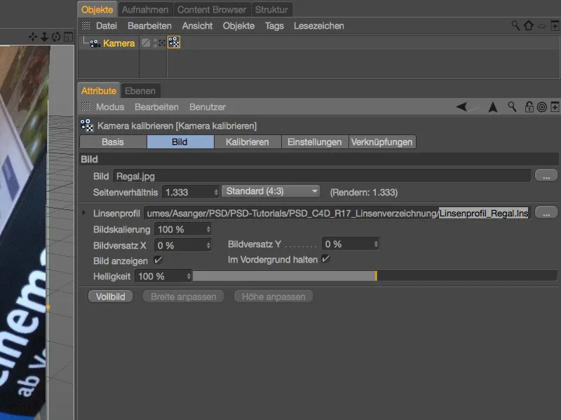
Let's leave the calibration aside for now and focus on the question of how we can get the rectified image into the scene during rendering. To do this, we conveniently create a correctly mapped background on the Calibrate pageusing the Background object button, including our shelf image as the assigned material.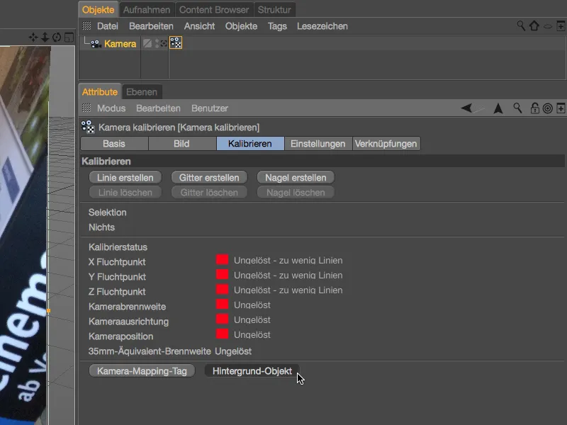
We open the material via the attribute managerand find our shelf shot linked as a texture in the color channel, albeit still in its distorted version. To rectify this texture with our lens profile, we load the lens distortion shader via the Effects arrow button menu.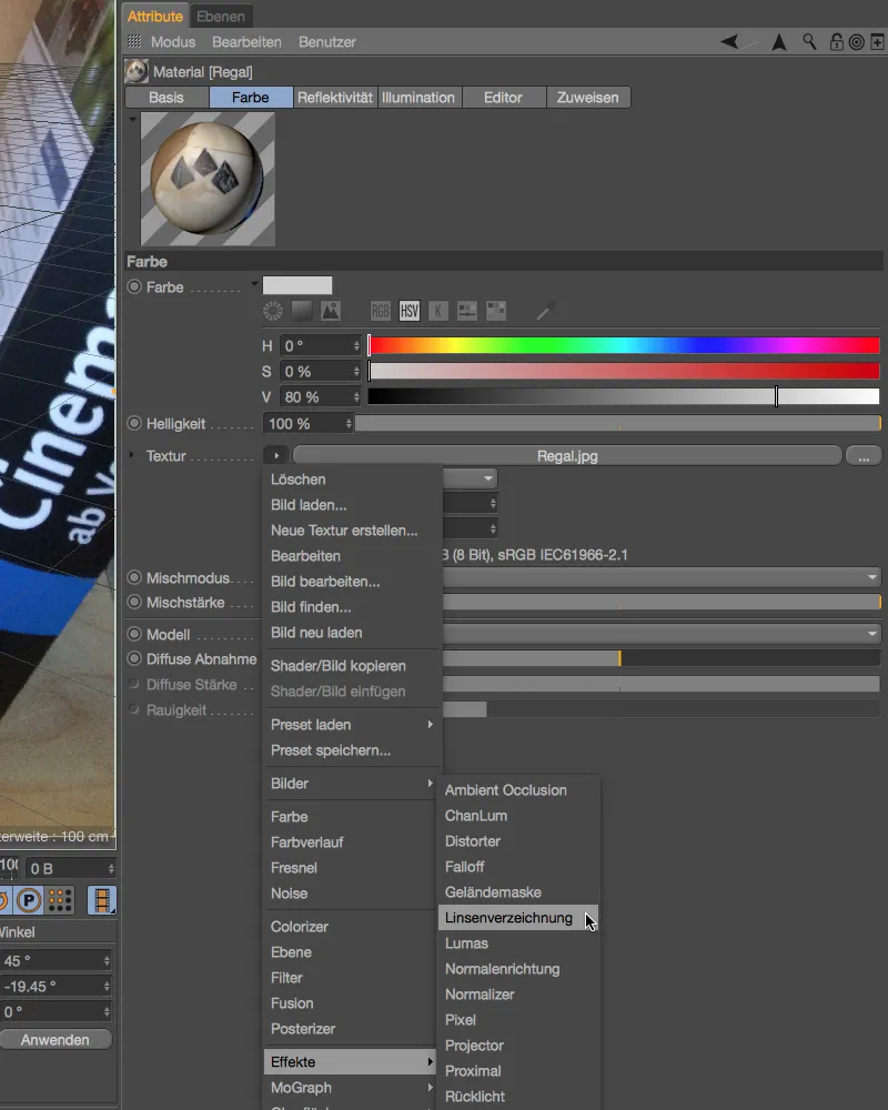
As we have not previously removed the shelf texture, it is automatically transferred to the shader as a texture when the lens directory shader is added. We now only have to load the lens profile into the corresponding field using the button on the right.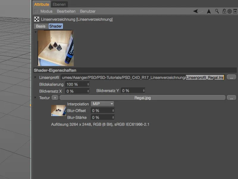
Now we can finally use the rectified image material for rendering. To calibrate the scene or the camera for the installation of 3D elements, we already have the rectified image in the camera calibration tag.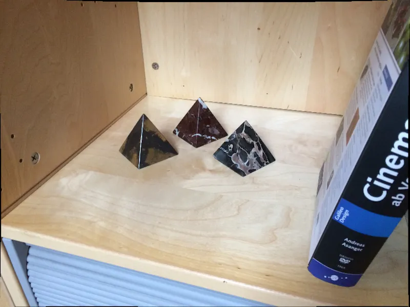
Similar to the camera calibration tag, we can of course also use the lens profiles we have created to rectify footage materialin the motion tracker. The rectification also gives us better tracking results.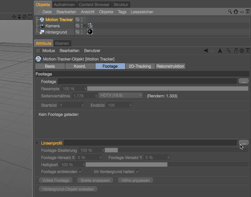
Using the lens profile to distort the 3D scene
As already mentioned, we can also use the lens profile we have created to slightly distort the 3D elements in order to adapt them to the original shot. In this case, of course, we do not distort the image in the camera calibration tag or in the material for the background.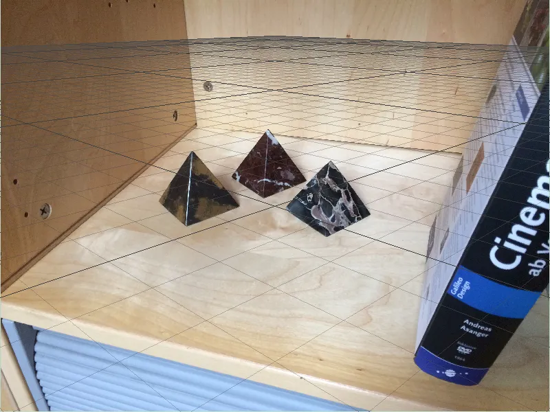
For this second example, I have therefore deleted the background object and removed the lens profile stored for rectification in the settings dialog of the camera calibration tag.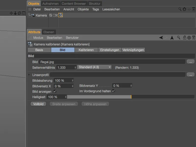
The camera or scene is therefore calibrated on the basis of the original image. The plane constraint for defining the X and Z axes is located on the shelf's footprint. I placed the nail for defining the origin of the scene in the back left corner.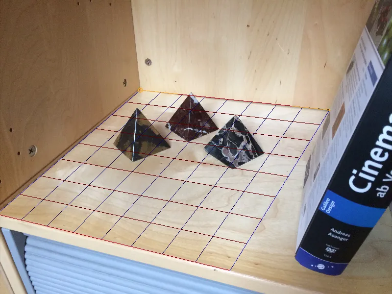
We also don't need any rectified image material to render the background. You can either simply create a completely new textured background object using the Create background button in the camera calibration tag, or you can delete the lens directory shader by simply copying the texture of the shelf from the shader into the texture fieldof the color channel.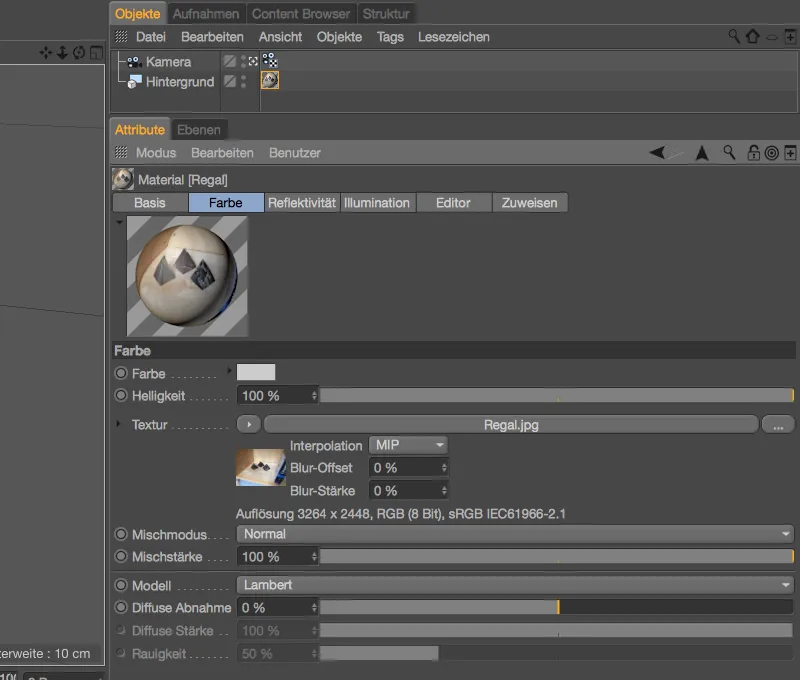
To match the three marble pyramids in the shelf shot, I created a pyramid object in Cinema 4D and added a bevel deformer to it to smooth the edges. A point light ensures that the lighting of the 3D pyramid object matches the shot.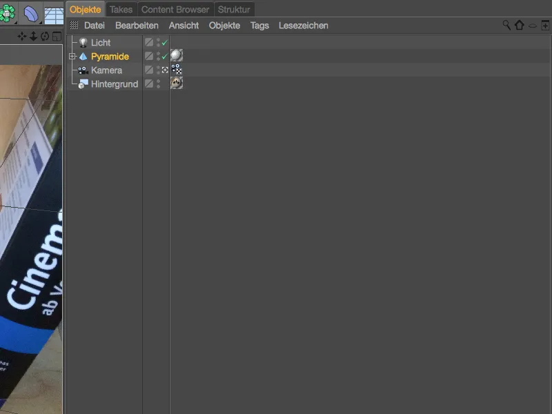
Thanks to the calibrated scene, the pyramid can be easily integrated into the scene; for my first test, I position it in the center of the image with the other three pyramids.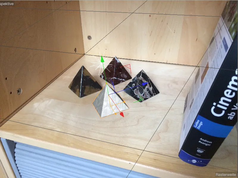
As you would expect, the positioned pyramid also cuts a good figure in the rendering, and the effect of the distortion caused by the optical lens is at its lowest here.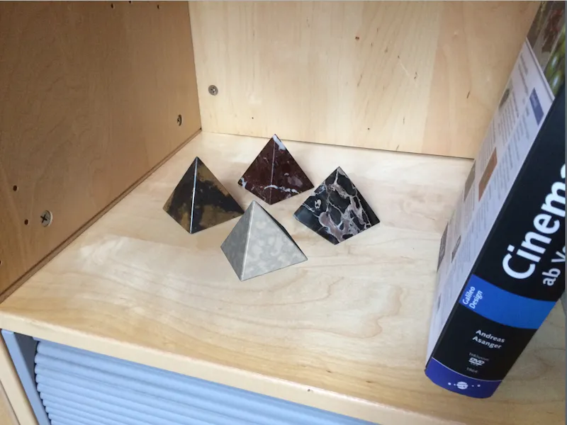
To ensure that the pyramid (and of course all other 3D objects) also behave according to the lens distortion at other points in the scene, we use a render effect to slightly distort the 3D elements. Like all other effects, the lens distortion effect is also located in the render presets, which we call up via the Render menu.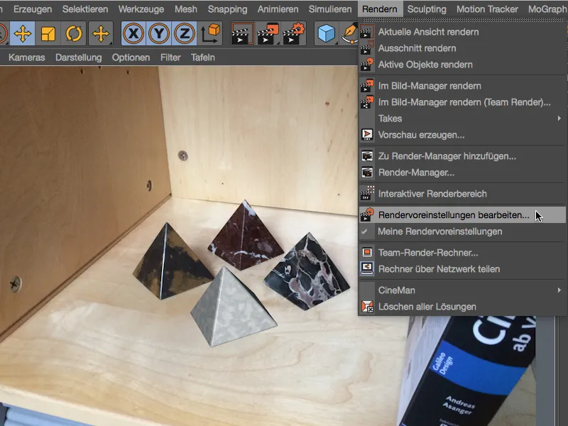
We activate the Lens distortion effect via the Effects... button in the render presets for rendering.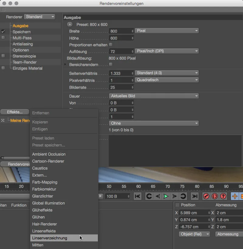
On the corresponding page of the effect in the render presets, we find the field for our lens profile. By adding the lens profile we have created, the lens distortion effect ensures that the 3D elements are distorted accordingly during rendering.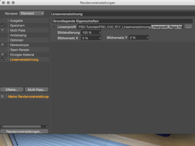
To test the interaction between the original image and the distorted geometry, we position the pyramid in the front right-hand corner of the shelf and trigger the rendering in the view or in the image manager.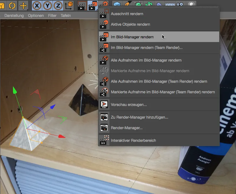
As we are dealing with an ordinary smartphone image and not a wide-angle shot, the effect of the distortion is naturally not extremely pronounced. Compared to the editor view, the pyramid appears somewhat flatter and minimally squeezed. Thanks to our lens profile, Cinema 4D now takes care of adapting the geometry to our original shot itself.