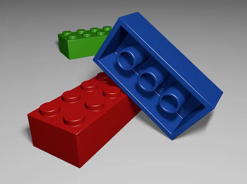
The starting object (and also the only object) of this tutorial is a parametric cube object. The aspect ratio specified in the X, Y and Z sizes corresponds to a well-known 8-unit Lego brick. To ensure that the units are not too small and impractical, especially when beveling later, I have worked at a scale of 100:1.
The specified side lengths turn our cube into the desired cuboid, the associated segmentations divide the cube in advance so that we get directly usable subdivisions when converting it into a polygon object.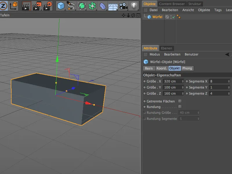
We convert it into a polygon object using the Convert basic object command or the C key , so that we now have an editable cuboid in front of us. Let's start with the top of the Lego brick.
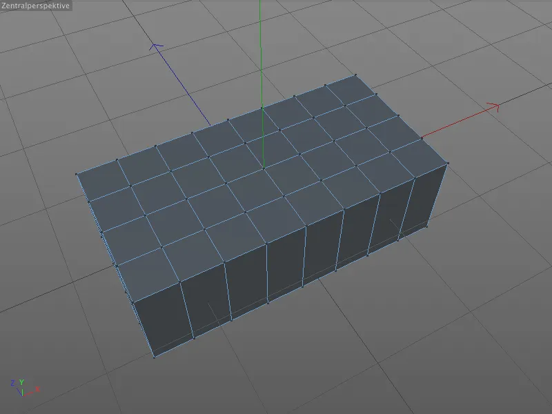
Modeling the studs on the top side
The bevel tool will be used for the first time in a moment. However, not to chamfer an edge or corner, but to round circles into the surface for us from selected points.
To do this, we select the eight points shown on the top of the cuboid in point editing mode by holding down the Shift key.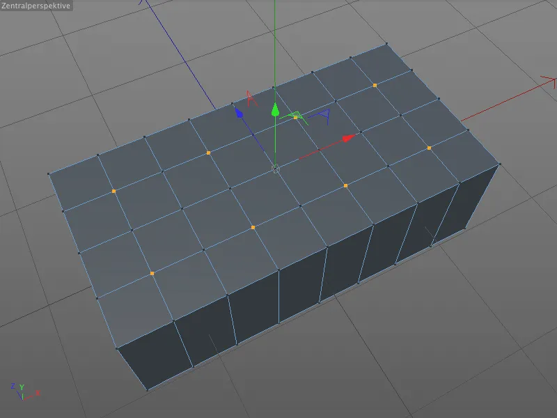
The Bevel tool can be found in the Mesh>Create menu, but as we use it very frequently, we prefer to remember the keyboard shortcut M~S (press the M and S keys in succession).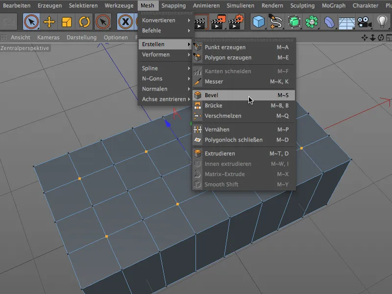
In the settings dialog of the Bevel tool, we can leave the Bevel and Offset modes at Bevel and Constant distance.
For the rounding, we enter the value 25 cm as the offset, which corresponds to the radius of the later circle. A subdivision of 6 ensures sufficient segmentation and therefore rounding of the circle.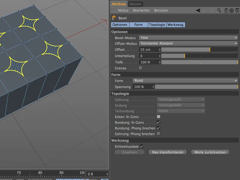
Before we adjust the decisive parameter and actually include a circle, we make a short stop for better understanding. After all, we currently have eight squares on the cuboid. These squares were created because each of the eight points was chamfered towards the adjacent neighboring points. To create a circle, we only need to turn these four chamfers per square ...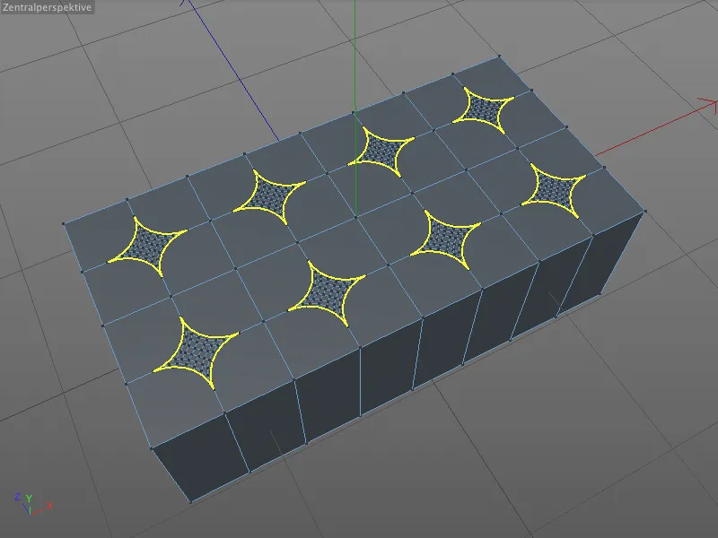
... and this is exactly what the depth parameter does for us. If we place a minus sign in front of the 100% depth , the chamfer rotates and we get the desired circles on the surface.
So that we can continue working with exactly these circles and not the polygons they contain, we activate the Corners option in the Topology section: N-Gons.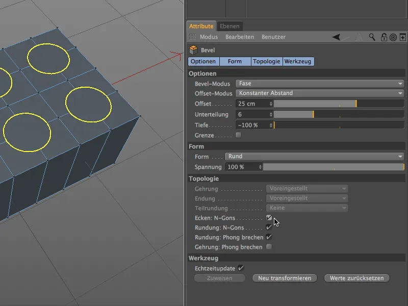
In this way, the points or edges contained do not interfere and the subsequent extrusion takes place without interference.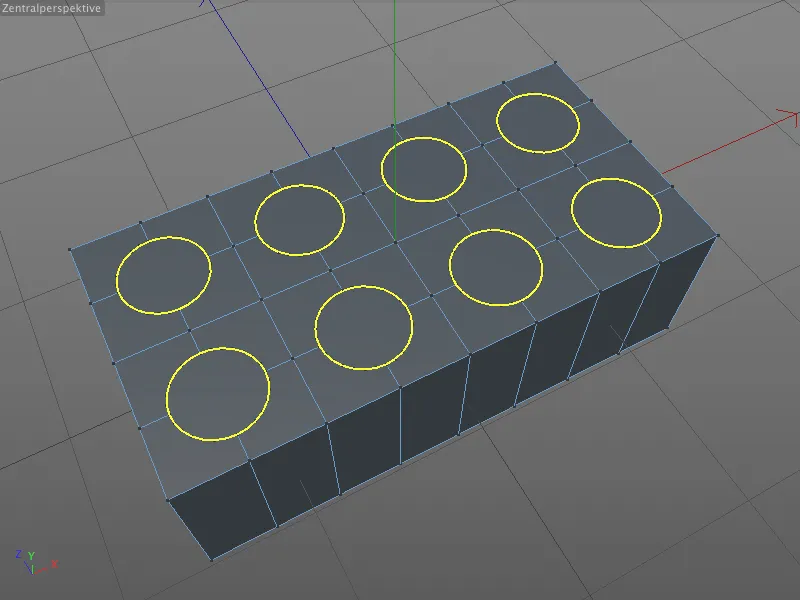
However, we must first select the polygon circles. To do this, we activate the live selection tool, activate the polygon editing mode and select the 8 N-gons one after the other by holding down the Shift key.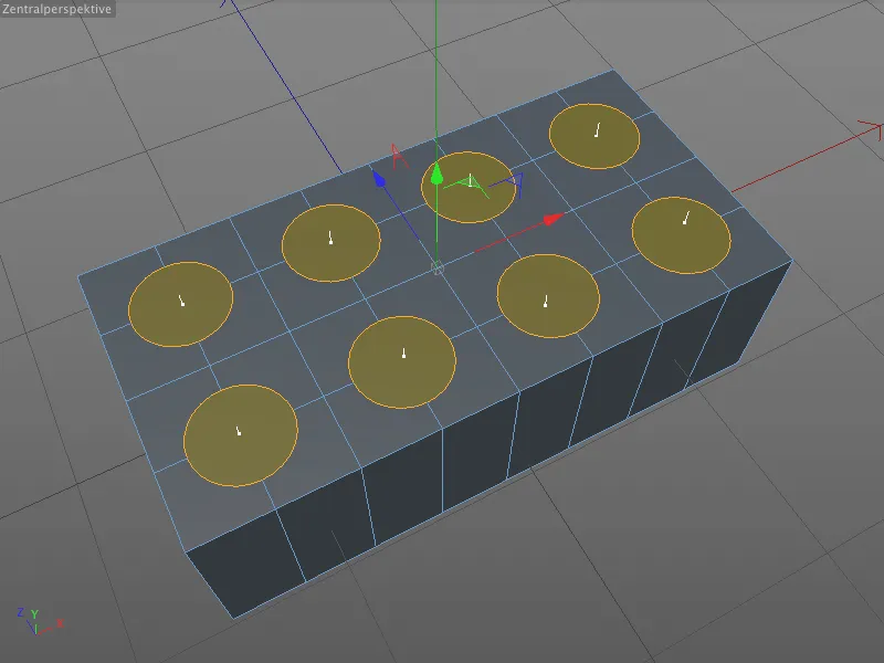
The extrusion upwards is of course carried out with the familiar Extrude tool ( D key ). In the corresponding settings dialog, we enter an offset of 15 cm to extrude the nubs from the surface.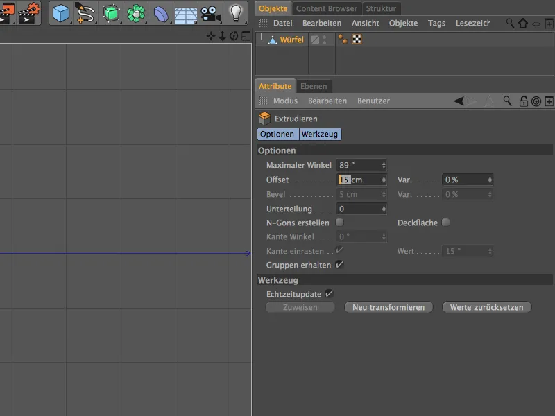
After this step, we have applied a total of eight studs to the Lego brick, albeit still with very unsightly sharp edges. But that's exactly what the bevel tool is for.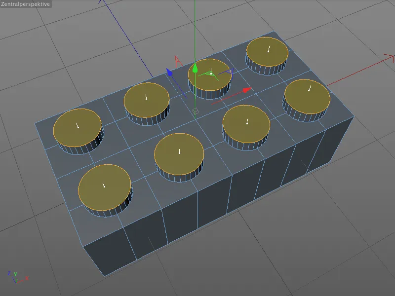
To convert the current polygon selection into an edge selection, simply hold down the Ctrl key and click on the Edit edges mode.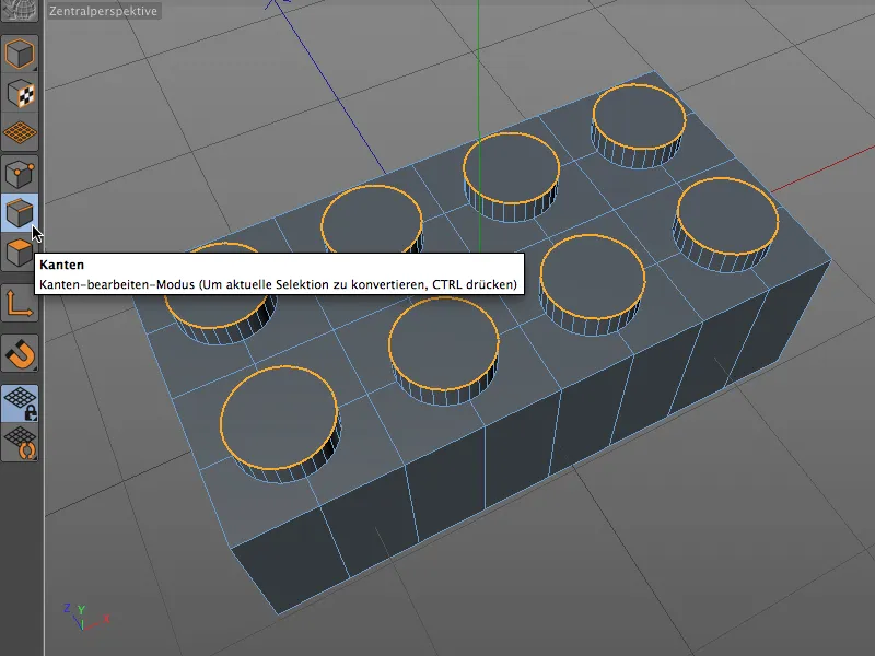
Now we activate the bevel tool ( M and S keys ) and obtain interactive handles for beveling on the nub edges. Let's take a quick look at how this works interactively in the editor. We use the mouse pointer to grab any point on the bevel edge...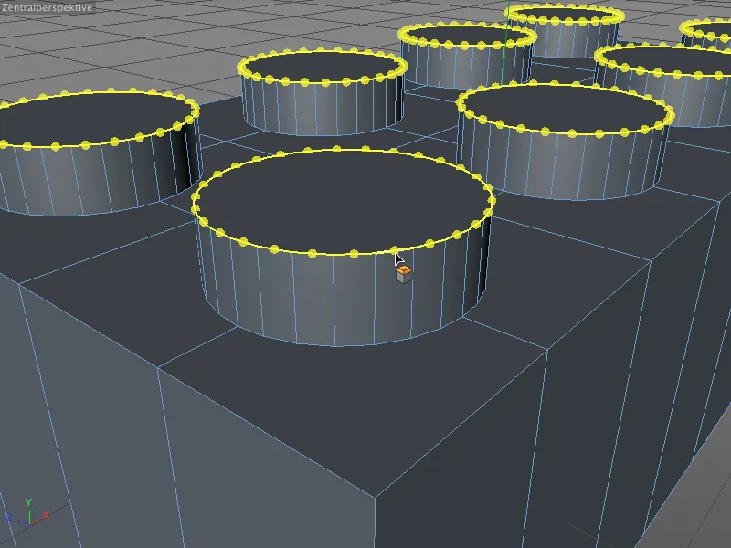
... and use the mouse to drag the height of the bevel, i.e. the offset value, from the edge. As long as we keep the mouse button pressed, we can modify the offset as required.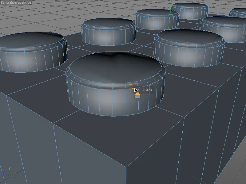
As soon as we release the mouse button, the offset is fixed (at least interactively). In the next interactive step, we can adjust the depth of the bevel. To do this, we move the mouse button to one of the rounded edges created during beveling. The tool symbol on the mouse pointer changes and indicates that we are now editing the bevel depth.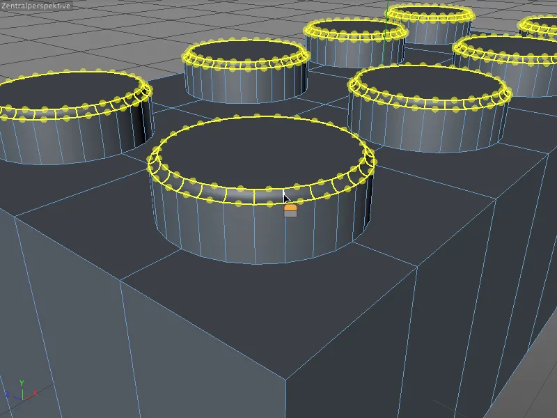
We can now change the depth of the bevel by dragging with the mouse. Here we still had a negative value from the circle bevel, which chamfered the edge inwards. However, this can be quickly turned to positive, i.e. outwards, interactively.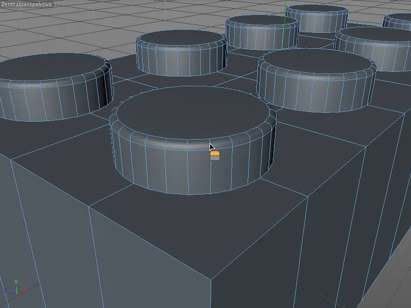
As soon as we release the mouse button here too, the value is set interactively. If we are not satisfied with the value, we can easily correct or fine-tune it using the settings dialog of the bevel tool. However, this is only possible until a new bevel is created or another tool is selected.
In our example, I have set the offset value to a smooth 2 cm, specified a subdivision of 4 and corrected the depth to exactly 100%.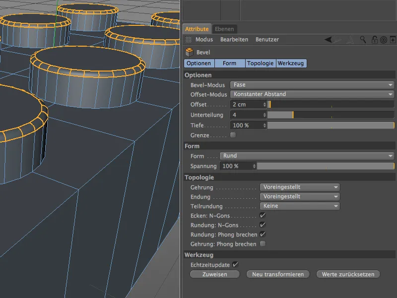
Now that we've smoothly beveled the upper edge of the studs, the transition to the top of the Lego brick is still missing. To do this, we take the loop selection from the Select menu and select the eight edges around the studs one after the other in edge-editing mode by holding down the Shift key.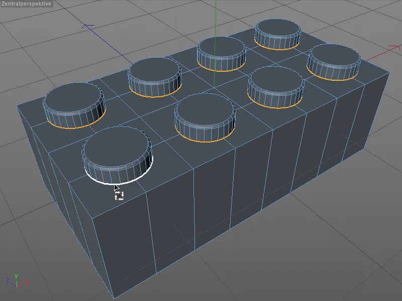
We activate the Bevel tool ( M and S keys ) and can very quickly determine an appropriate value for the offset interactively, ...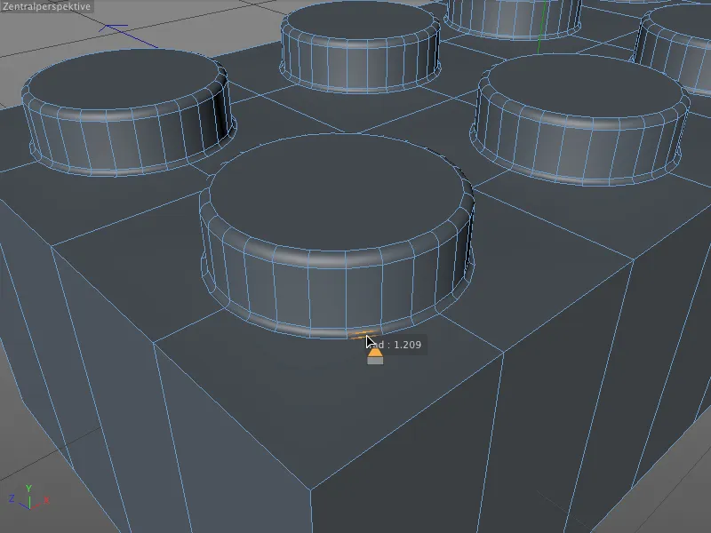
... which we then smooth to a value of 1 cm using the attribute manager and add a sufficient number of subdivisions. Three subdivisions should be enough for these very small seams on the studs.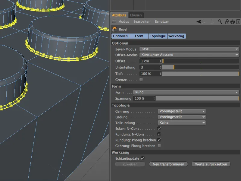
Modeling the cavity on the underside
With the exception of the outer edges, the top side has now been modeled, so we can now take care of the more complex underside of the Lego brick. At the moment, however, we don't even have a cavity in which we could place the important tubes for the plug connection.
First, we rotate the view in the editor so that we have a good view of the underside of the building block. Then we activate the polygon editingmode and select all the polygons on the underside of the block.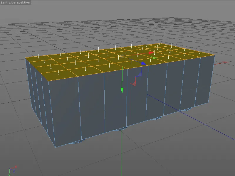
With an inner extrusion, we now create a new circumferential edge based on the material thickness, but protect the existing inner points from unwanted scaling or displacement.
We obtain the inner extrusion tool via the I button and enter an offset value of 15 cm for the future wall of the Lego brick in the associated settings dialog.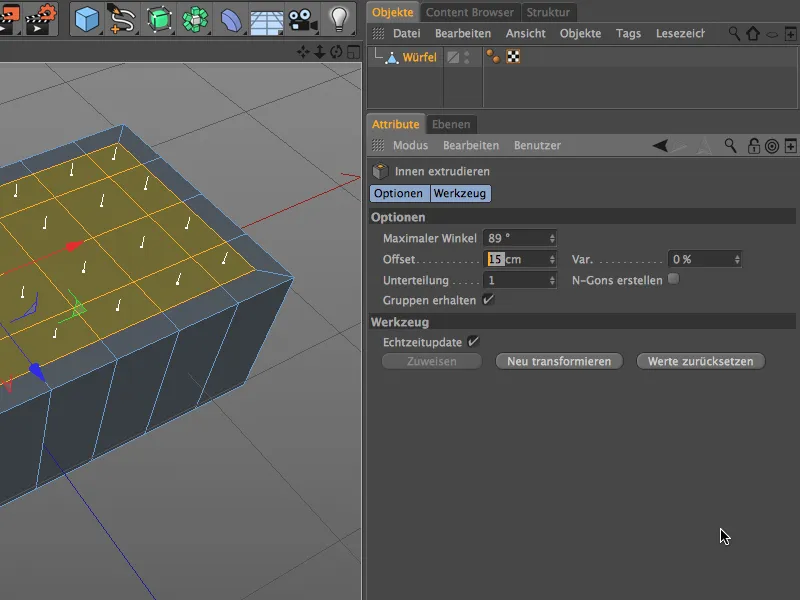
Here is a clear overview. The existing segmentations are unchanged after this step, so that everything will continue to correspond to the finished top of the Lego brick in the following elaboration.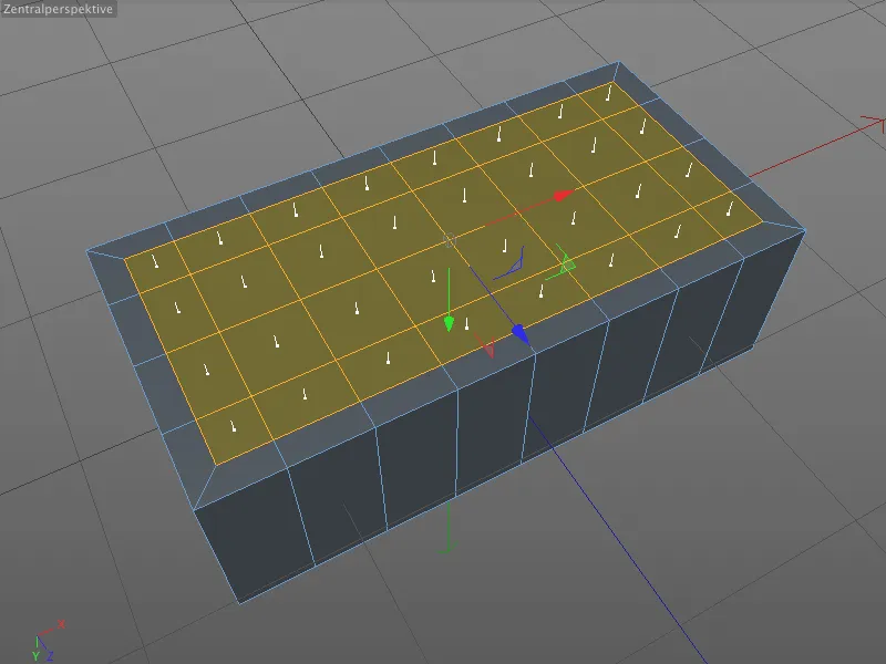
The existing polygon selection remains active, as we need it for the cavity in the next extrusion step. We simply switch to the normal extrude tool ( D button ) and enter an offset value of -90 cm in the settings dialog.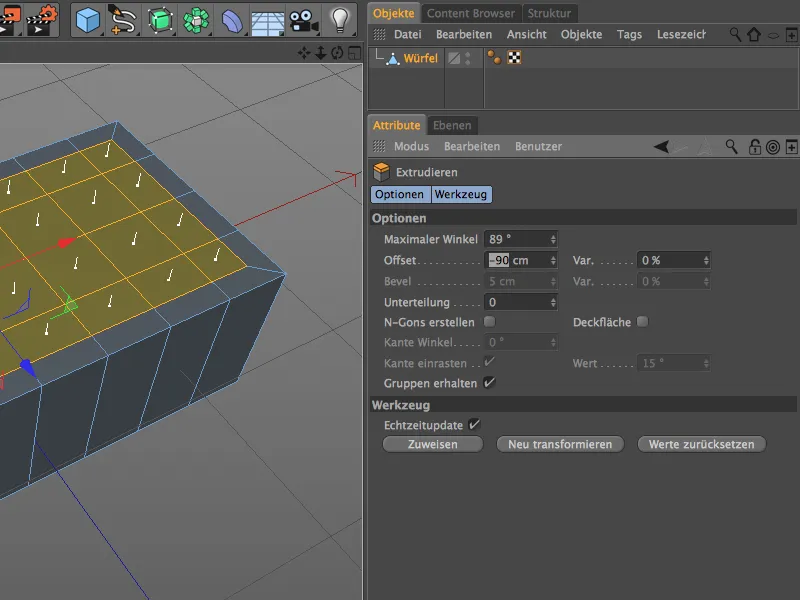
Now that the much-needed cavity is in place, let's move on to the further elaboration of the Lego brick interior. Strictly speaking, the cavity has not yet been fully developed, as the studs are also noticeable on the underside with small indentations.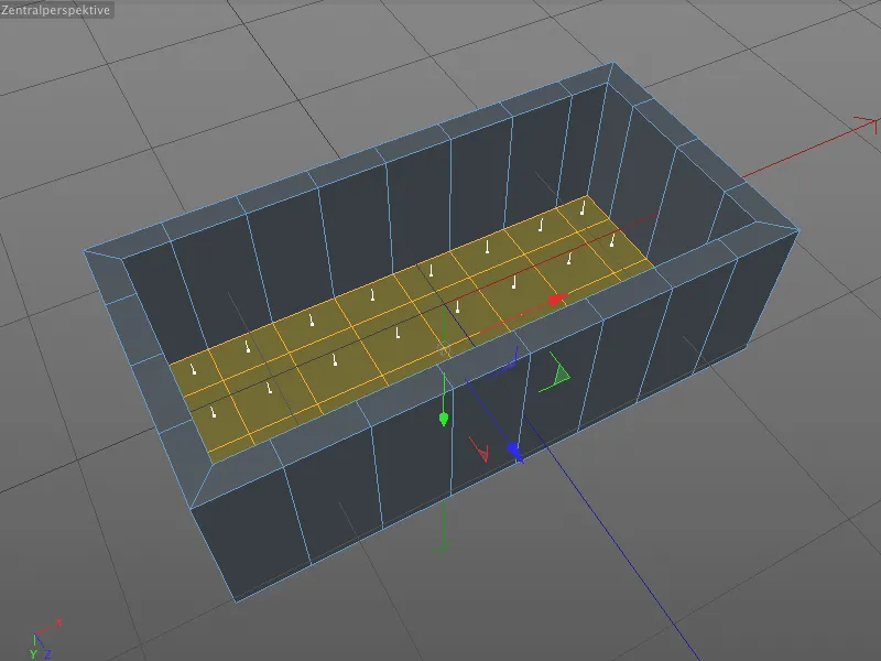
Similar to the top side of the Lego brick, we select the eight points on the inside in the center at the position of the studs in point-editing mode. As we have avoided geometric displacements during the extrusion of the cavity, we can be sure that all positions are correct.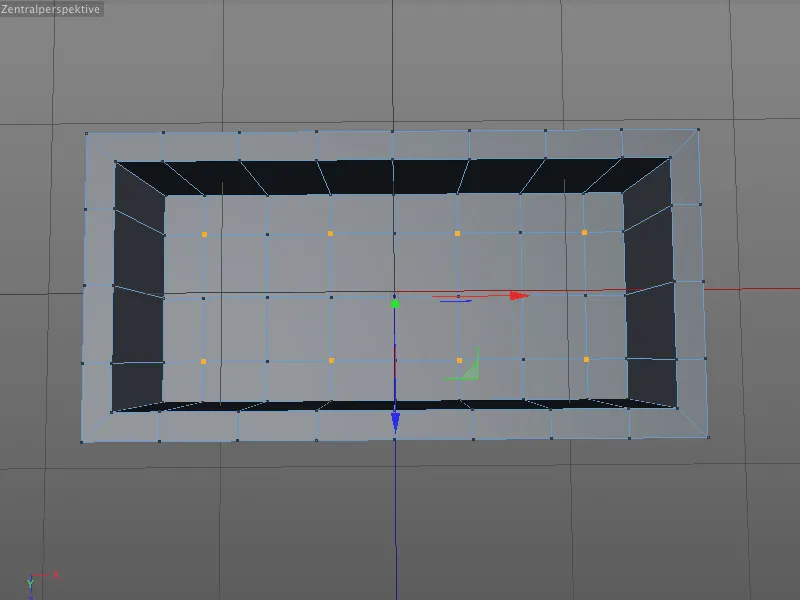
We call up the bevel tool ( M and S keys ) and this time we restrict ourselves to entering the correct parameters in the attribute manager. The radius of the circles results from the offset value of 10 cm, the subdivision of 5 is too high rather than too low and the depth of -100% again ensures that the bevels join together to form a circle.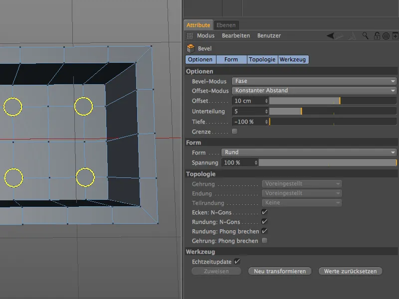
After beveling the circles into the surface, we switch to the polygon edit mode to select the eight N-gons for the extrusion of the cavities within the studs.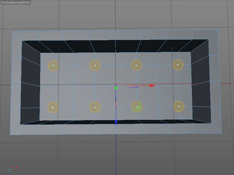
We call up the Extrude tool ( D key ) and enter an offset value of -15 cm in the associated settings dialog. Anyone who has done the math knows that we are already a little way inside the studs.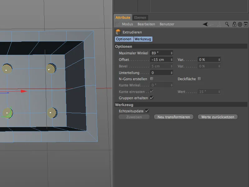
In order to use this selection for the inner edges, we switch from polygon editing to edge editing mode, as usual by clicking while holding down the Ctrl key, and obtain the corresponding edge selection.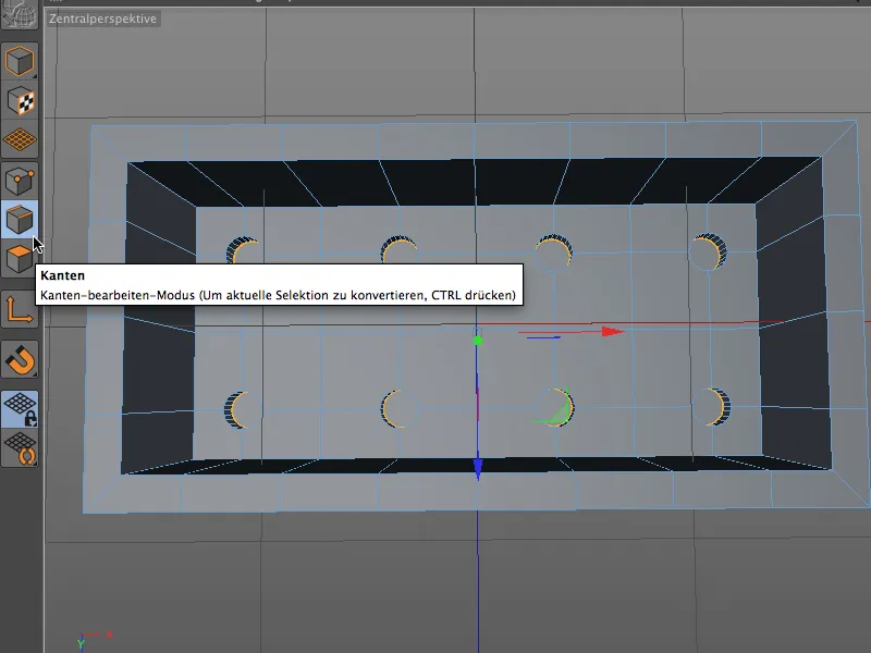
Admittedly, you will rarely see much of the inner edge of the nub cavity, but the bevel tool ( M and S keys ) makes things really easy for us. An offset value of 1 cm with a triple subdivision is completely sufficient.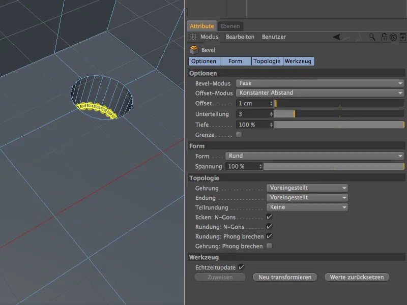
We also need the bevel tool for the transition of the studded cavities into the underside of the Lego brick. Before we do this, however, we need to select the eight circles on the bottom of the Lego brick with the loop selection in edge-editing mode while holding down the Shift key.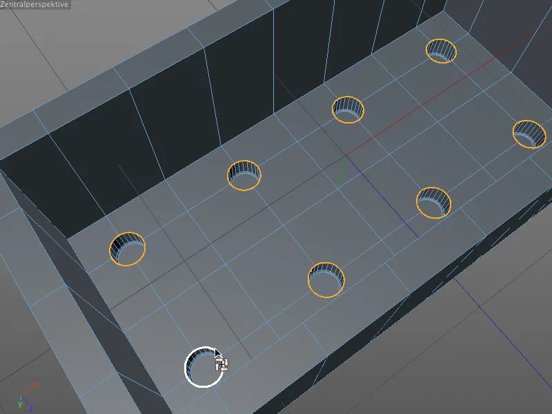
It's a good thing that the bevel tool remembers the settings from the previous editing step, because after calling up the tool we only have to click the Transform new button to get the matching bevels on the bottom of the Lego brick interior.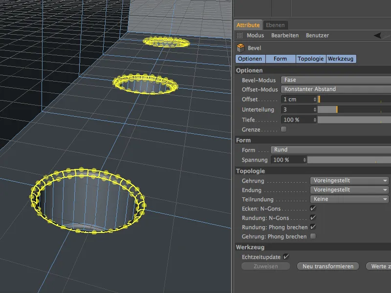
Modeling the fastening tubes
The hollow fastening tubes in the interior of the Lego brick are very important for the stability of a Lego construction. The 8-brick has a total of three of these tubes, each centered between the studs.
We switch to point-edit mode and use the live selection tool to select the three points on the inside at these locations.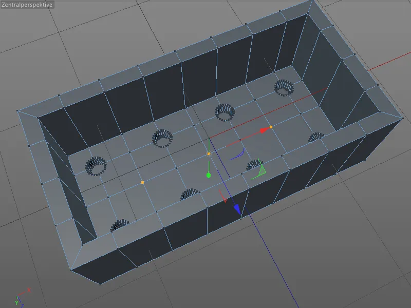
From these three points, we create polygonal circles in the geometry by beveling, from which we extrude the fastening tubes. The procedure is familiar: we activate the bevel tool ( M and S buttons), specify the radius of the tube using the offset value of 30 cm and select a relatively high subdivision of at least 6. Compared to the studs and indentations, the tubes are relatively large and clearly visible, which is why we should not skimp on subdivisions here.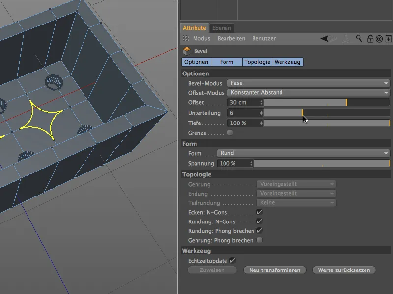
Now we set the depth to -100% and obtain the desired circular N -gons for the extrusion of the hollow fastening tubes.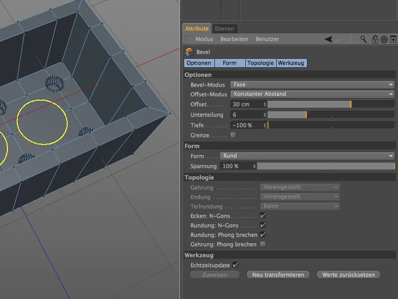
To extrude the N-gons, we switch to polygon editing mode and select the three circular polygons with the live selection tool.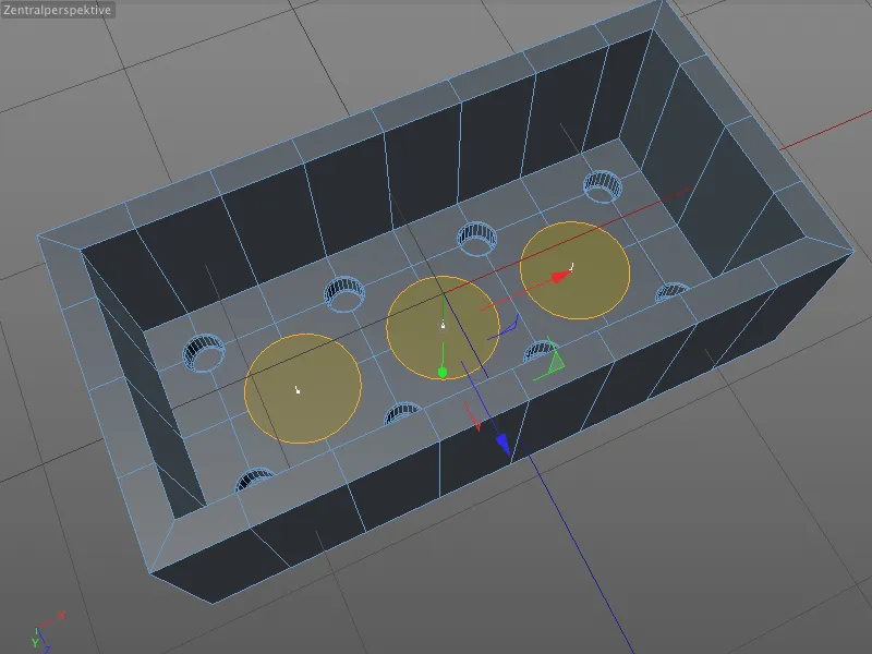
In the settings dialog of the Extrude tool, we assign an offset value of 90 cm for the upward extrusion. After we had created the hollow space of the Lego brick with a negative extrusion of -90 cm, the upper edge of the tube is now flush with the lower edge of the Lego brick.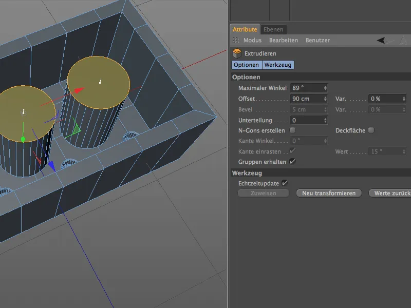
To turn the extruded pin into a tube, we now add an inner extrusion of the selected polygons. We call up the inner extrusiontool using the I button, an offset value of 8 cm reduces the inner radius of the future cavity by this desired value.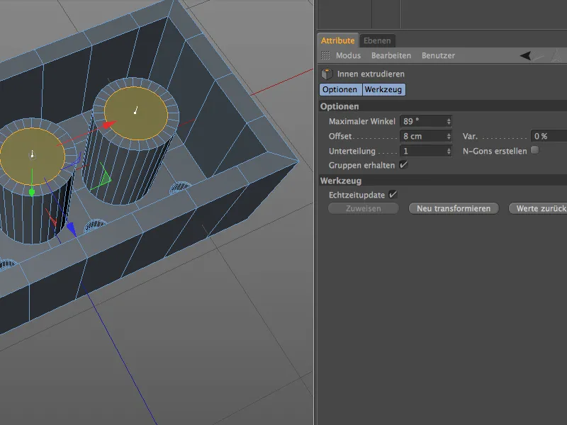
We now create the cavity for the tube with an immediately following normal downward extrusion ( D key). The value of -90 cm corresponds to the height of the interior of our Lego brick, so that we are once again flush with the inner surface.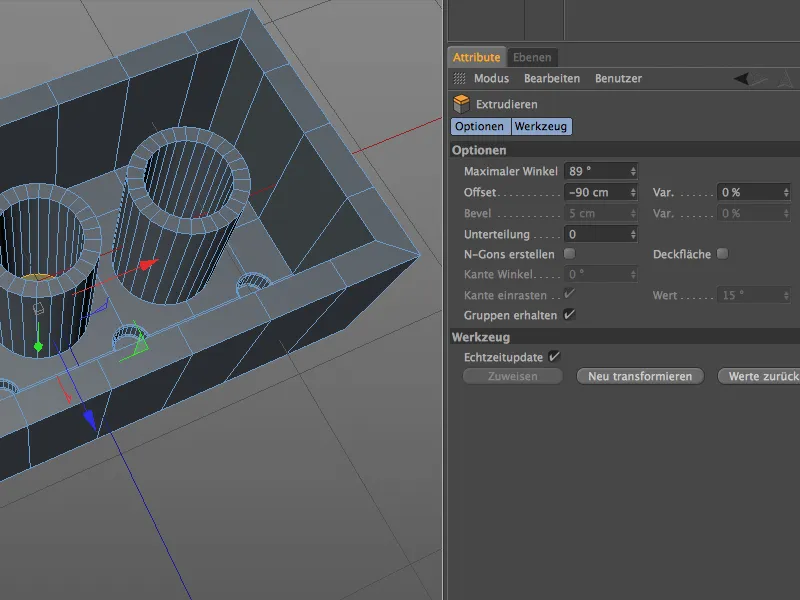
As the three polygons are still selected at the moment, we take the opportunity to convert the current polygon selection into an edge selection. To do this, hold down the Ctrl key and switch back to edge editing mode.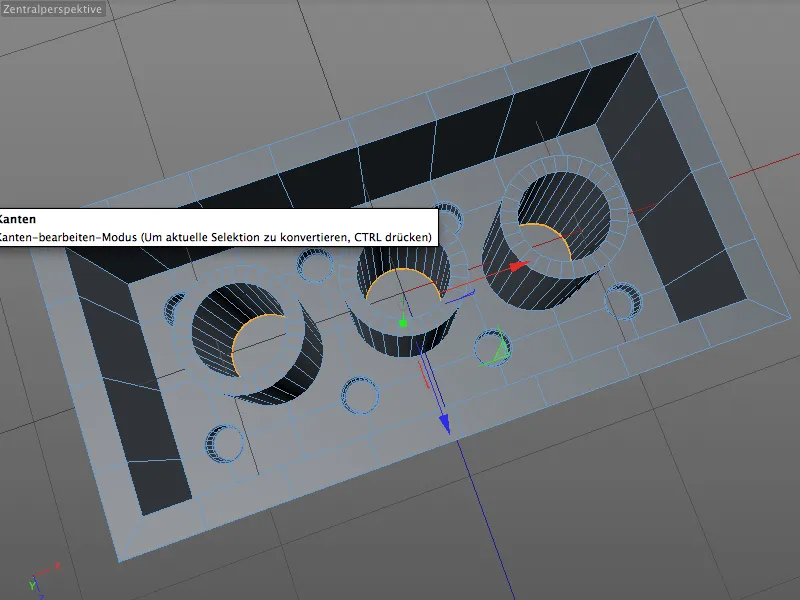
We can now easily edit the lower edge in the interior of the tube. Use the M and S keys to call up the bevel tool again and assign an offset value of 2 cm with a maximum subdivision of 4. Don't forget to set the depth value to 100% so that the rounding at the transition to the surface is concave.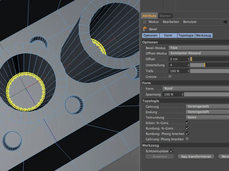
The upper edges of the mounting tubes are relatively rounded so that the Lego bricks are easy to fit together. To bevel these edges as well, we select the 6 circular inner and outer edges on the top of the three tubes using the loop selection and holding down the Shift key.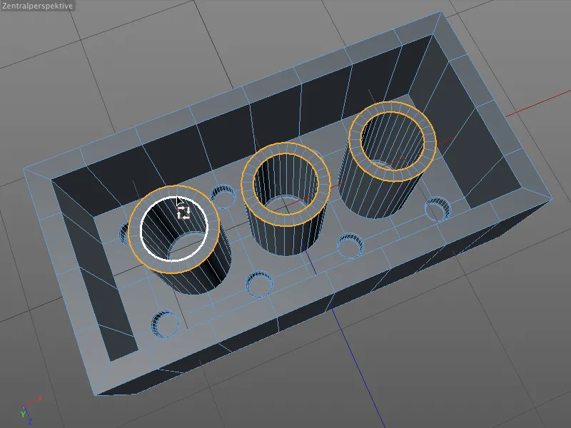
We can complete the beveling of all six edges of the tube in one go, as the bevel radii should be identical on the inside and outside. We therefore call up the bevel tool ( M and S buttons ) and assign an offset value of 3 cm for the bevel height. As the top of the mounting tube will be clearly visible, the bevels are also given a sufficiently high subdivision of 5. The depth value of 100% matches the inner and outer edges of the tube.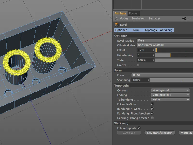
Let's give the three tubes a smooth transition to the inner surface of the Lego brick. Using the loop selection, we select the three circular edges together by holding down the Shift key, ...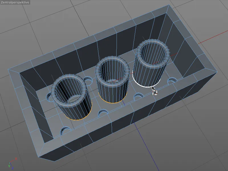
... call up the bevel tool ( M and S keys ) and apply a bevel with an offset value of 2 cm and a fourfold subdivision for the soft transition to the surface.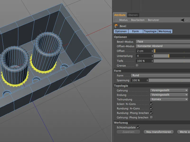
After this step, the three hollow mounting tubes of the Lego brick are now complete. The perfectly sharp inner and outer edges of the Lego brick are still a problem.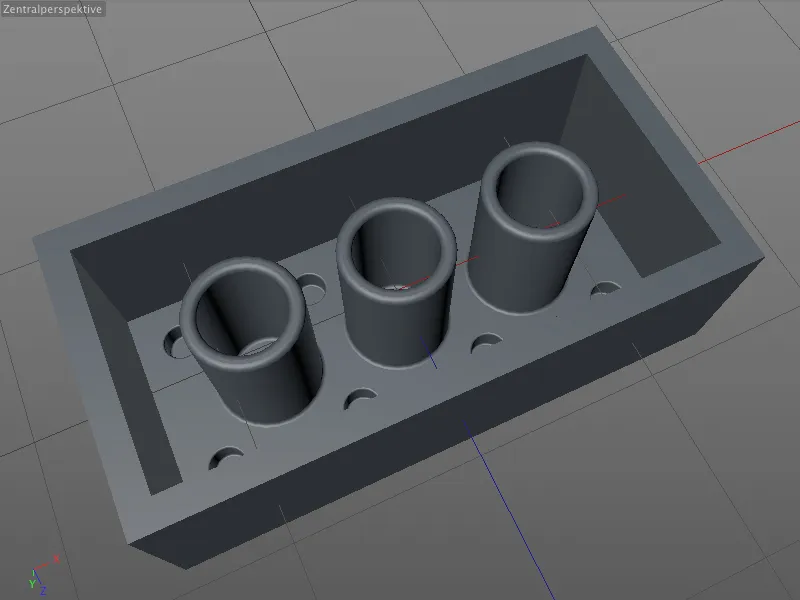
Beveling the inner and outer edges
As simple as these last tasks of this tutorial may sound, it is important when beveling that we always consider the relationship of the bevel edges. In the case of the interior, we not only have to consider the edges running parallel to the XZ plane on the top and bottom of the Lego brick, but also the corners perpendicular to it.
In order to obtain homogeneous chamfers here, we select and bevel these interior edges together. To do this, we first select the circumferential edges on the top and bottom using the loop selection and then select the four edges on the corners of the interior by holding down the Shift key and using the live selection.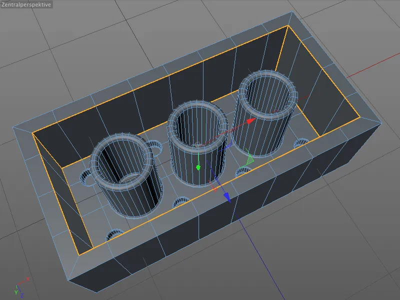
Even though Lego bricks are quite sharp-edged, a small chamfer contributes greatly to the realistic appearance of the model. The edges to be beveled are already selected, so we only need to call up the bevel tool ( M and S buttons ) and enter a small offset value of 2 cm for a triple subdivision.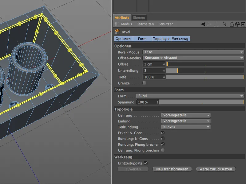
Let's now take a quick look at the critical detail of the abutting bevel edges. In the settings dialog of the bevel tool, we have several options for designing this corner on the topology page under mitre. In our case, the preset mit er is a good choice as it generates a very soft, unobtrusive corner. You are welcome to take this opportunity to test and get to know the other mitering methods.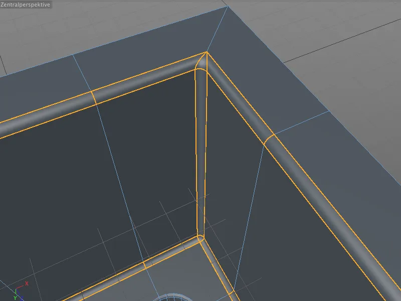
A look at the model without selection confirms that the beveled inner and outer edges are clean and not too soft or round. The interior of the Lego brick is now fully modeled, so we can now turn our attention to finalizing the top.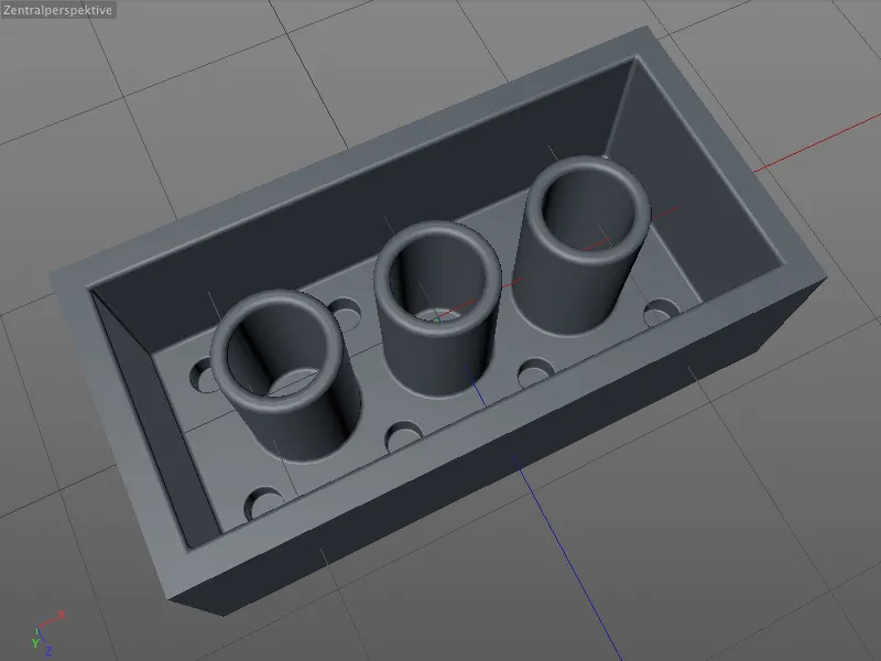
When finalizing the top or outside of the Lego brick, it is again important to ensure that the bevel edges are connected . As with the inside, we again have perpendicular edges, which is why we first select the outer edges on the top and bottom using the loop selection and then select the perpendicular outer edges of the Lego brick by holding down the Shift key.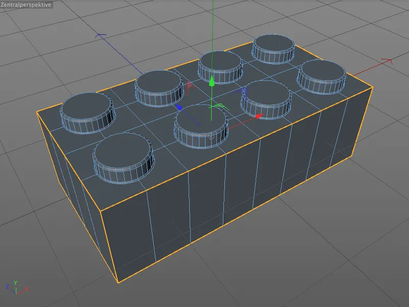
Now we can call up the Bevel tool ( M and S keys ) and simply leave or adopt the offset, subdivision and depth values already used for the inside of the Lego brick.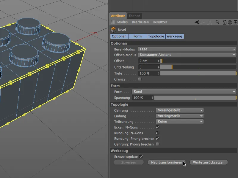
If we zoom in on a corner of the Lego brick, we can see for ourselves that the preset miter method also generates smooth and inconspicuous edges and corners on the outside of the brick.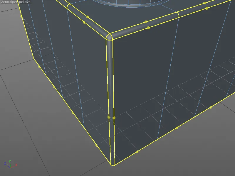
After this final processing step, our Lego brick is finally finished. Only the company logo on the studs is missing, but that is irrelevant for this tutorial on beveling with CINEMA 4D Release 15.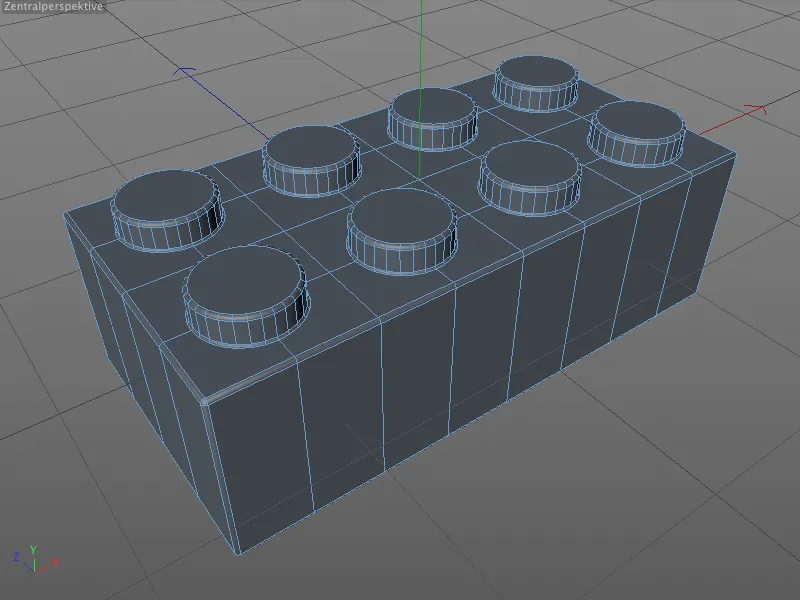
With a few bright colors, we now have our first bricks in our Lego box. Of course, all other building block variants can be realized in the same way - provided that the segmentation is appropriate.
One conclusion of this tutorial should be that with the new bevel tool we finally have a great tool for technical modeling at hand and are no longer dependent on experiments with the subdivision surface generator (HyperNURBS).