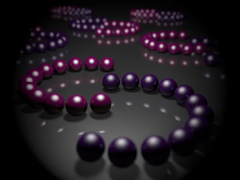
In order to get to know the special features of the physical camera in the best possible way, I have prepared a special scene with lots of shiny and reflective spheres. You can find it as a working file "PSD_C4D_R13_Physik_Kamera.c4d" so that you can easily understand my settings.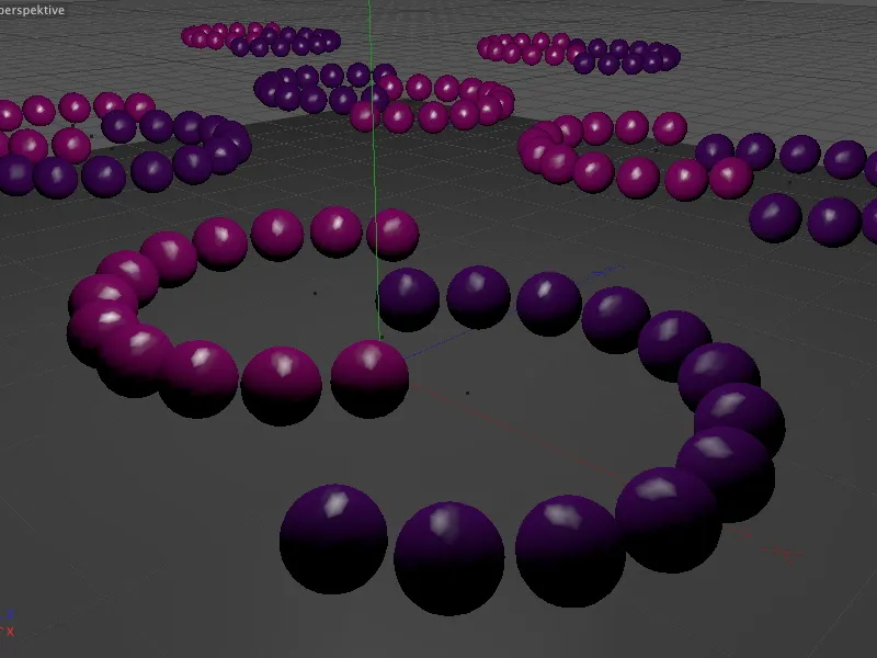
Structure of the example scene
The physical renderer, which includes the physical camera, is part of all CINEMA 4D versions except the basic version Prime. I used MoGraph to create the spheres in the scene. For owners of the Visualize version, which does not include MoGraph, this structure is also implemented in the scene without MoGraph.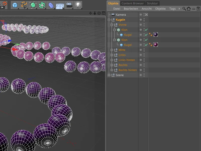
The colored spheres were distributed in semicircles in the scene using radial clone objects. If you wish, you can also create other formations using different radii, angles or clone numbers.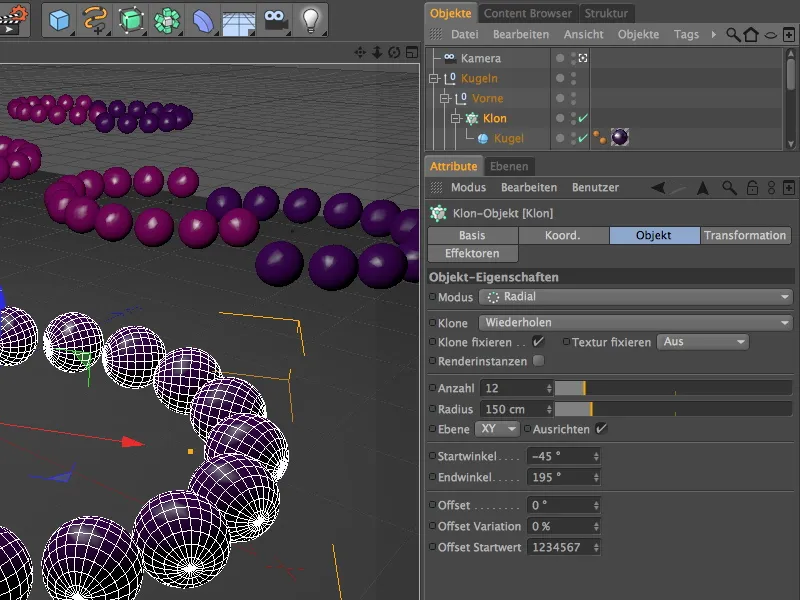
As already mentioned at the beginning, the highlights play a decisive role in our example. Together with the depth of field of the physical renderer, they have a decisive influence on the bokeh, i.e. the appearance of the blurred area.
In addition to the reflection, a sharp, high highlight is also set for the two materials of the spheres, which is supported by a single light source positioned centrally above the scene.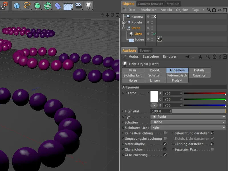
As we do not want to compromise on quality in this tutorial, the light source provides surface shadows. By increasing the minimum and decreasing the maximum number of samples, we keep the render time well in check. A density of 80% is sufficient to ensure that the shadow areas do not appear too dark.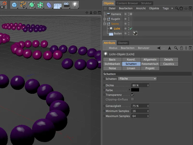
A test rendering shows the current state of the scene without a physical camera or renderer. There is no blurring either close up or in the distance. We now want to change this with the physical camera.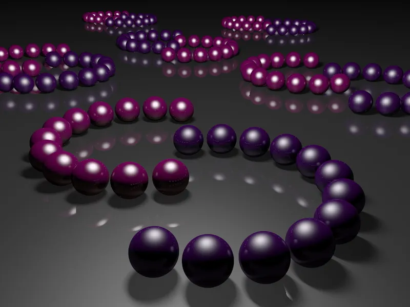
Activating and setting the physical camera
A separate camera is already installed in the scene for this tutorial. Before we turn our attention to the physical functions of the camera, let's take care of setting the focus distance - this controls the area of maximum sharpness in the image.
To do this, we deactivate the currently active camera by clicking on the camera icon in the object manager so that we can control the camera via the editor view.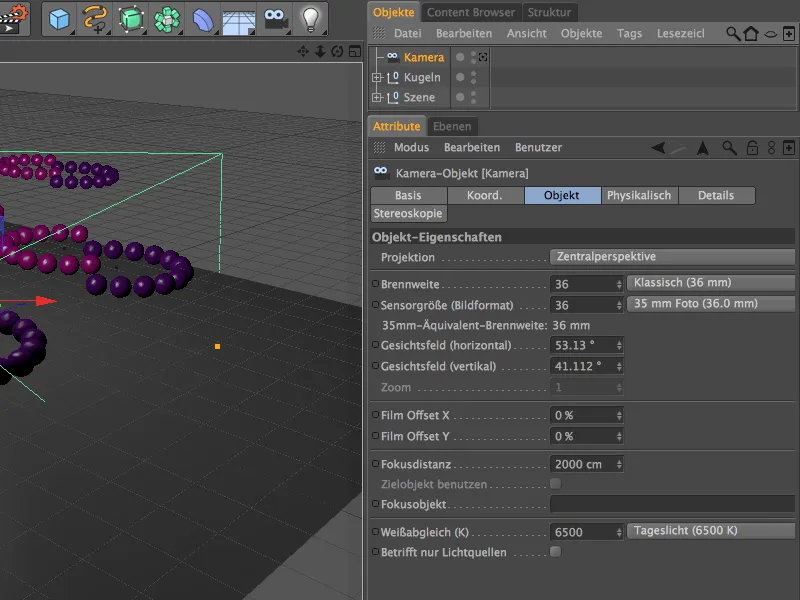
Look for a perspective that is as clear as possible and in which you can easily reach and adjust the focus distance using the middle orange gripper.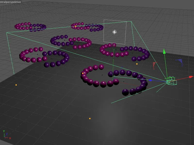
Now set the focus distance to the distance at which the balls should be in the zone of maximum sharpness. For my first rendering, I opted for the end of the first purple ring of spheres. This allows us to assess the depth of field near and far in the scene.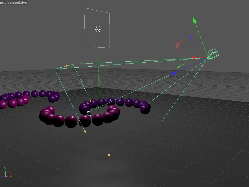
A look at the settings dialog of the camera object proves that only the focus distance has been changed. We don't want to change anything else in the standard camera settings; the parameters on the neighboring Physical page are now more important.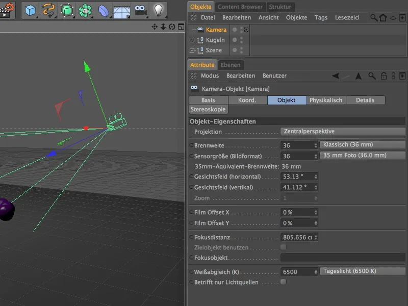
Unfortunately, this page is not particularly cooperative. Before we can make any physical settings on the camera, we first have to activate the physical renderer.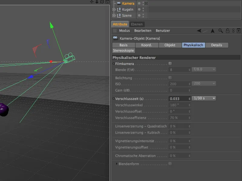
To do this, we call up the render presets in the Render menu ...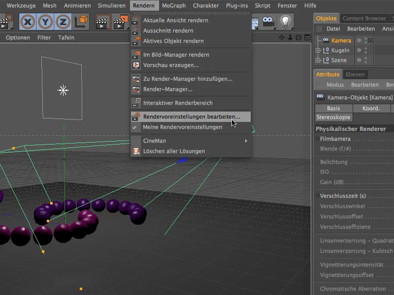
... and switch to the Physical entry in the Renderer menu in the left-hand column.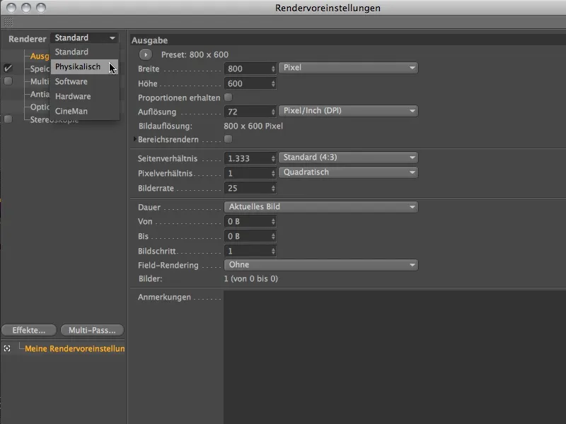
As we primarily want to deal with the depth of field of the physical renderer in this tutorial, we will only activate the Depth of field option on the Physicalpage of the render presets.
For the sample quality, the medium quality preset should give us a first impression before making any further adjustments.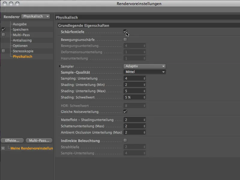
Now that the physical renderer is active, the parameters on the physical page of the camera settings dialog are also enabled. As the name physical suggests, the settings for Blender, exposure and shutter speed are based on a real camera.
If the aperture values available in the Blender menu are not sufficient, you can of course use your own values. This is often the simpler way instead of scaling an entire scene.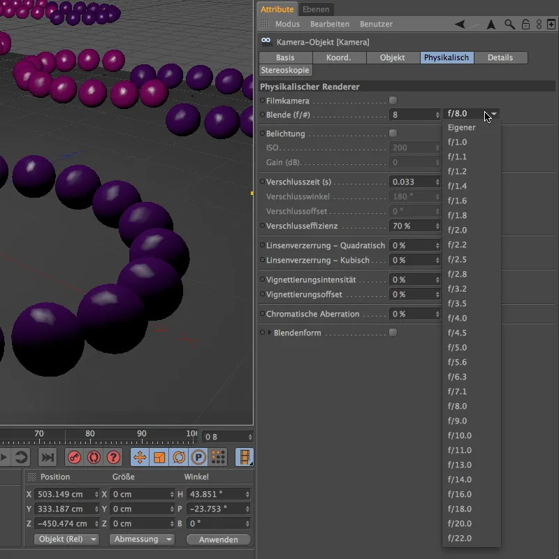
My tutorial project is an example of this. We use the Blender to control the strength of the depth of field. To achieve a meaningful result right away, I'm using an aperture of 0.1 here.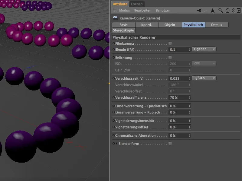
After clicking on the render button, the physical renderer does a great job and gives the blurred areas a clear depth of field. The distance we defined as the focus distance up to the end of the front purple ring, on the other hand, is sharp, as desired.
In the rear area, it is easy to see that the quality of the blur is not yet satisfactory.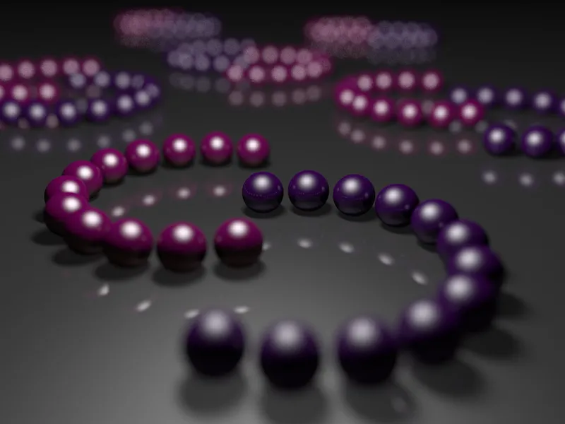
In order to resolve these areas more finely, we set the sample quality one level higher to High in the render presets.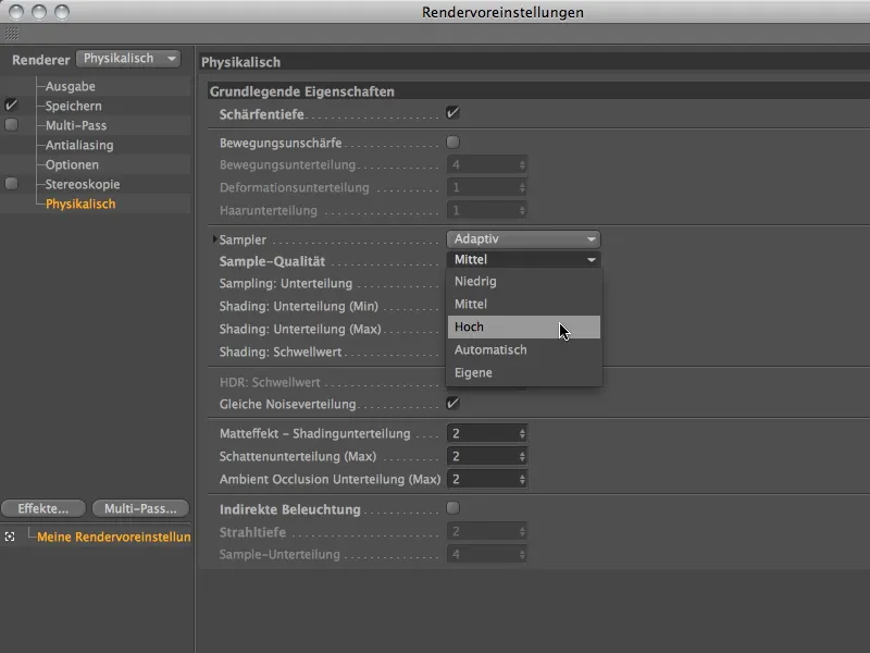
The increased sample quality shows a clear effect after clicking on the render button again. Of course, the render time has increased slightly at the same time, but for a good purpose: the blur area is now much finer and softer.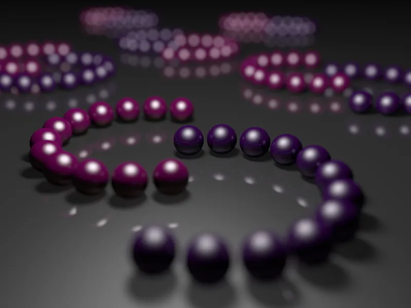
Varying the areas of sharpness
Now let's take a look at how we can shift the focus range. In this variant, the middle rings should be in focus. To do this, we simply change the Focus distance parameter in the settings dialog of the camera object on the object page. Alternatively, you can of course also modify the focus distance interactively using the orange camera handle in the editor view.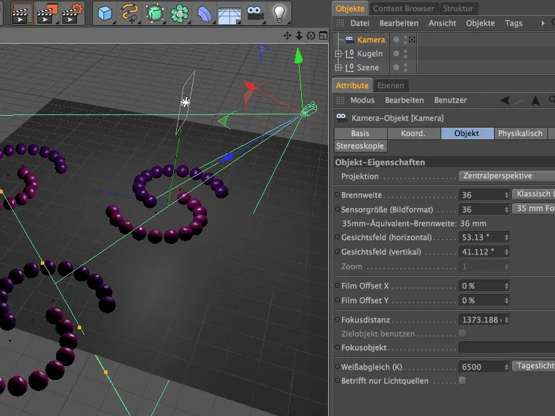
We render with the identical render settings and immediately see that the middle spherical rings are now in focus. While the blurring near the camera has increased, the rearmost spherical rings are easier to recognize.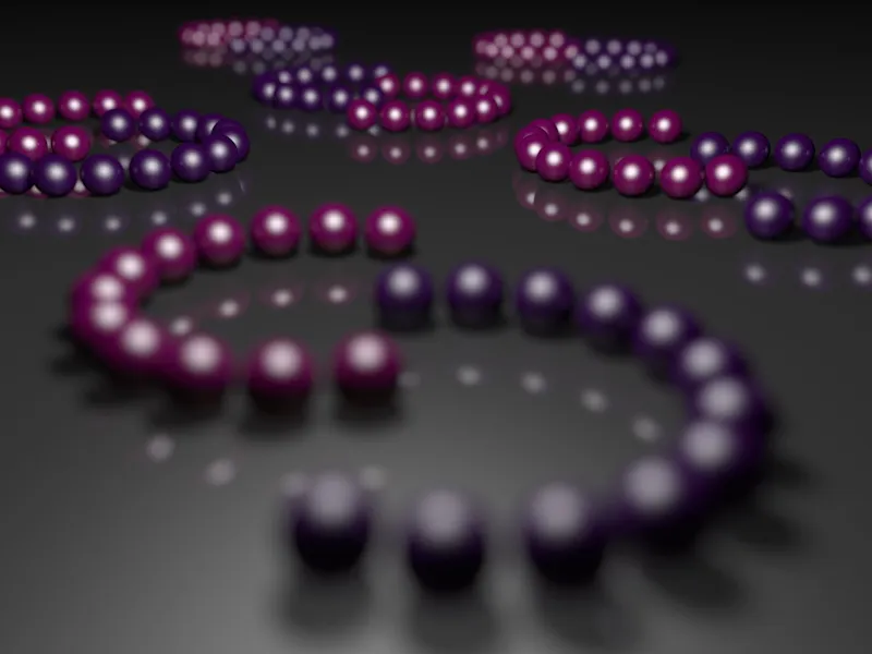
For the next comparison, we reduce the focus distance in the next test to the foremost spheres of the first ring.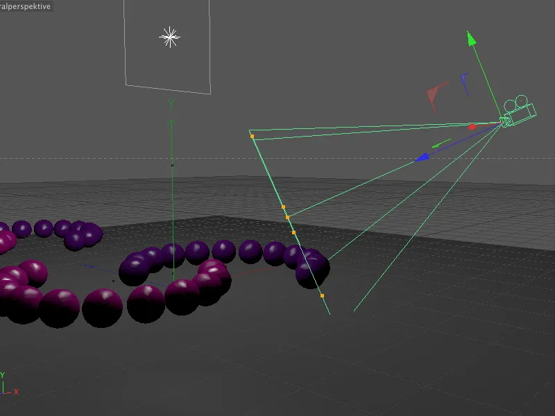
As expected, in this variant only the spheres just in front of the camera are in focus; shortly afterwards, the blurring increases all the way to the rearmost rows, where only the highlights mentioned at the beginning can be seen.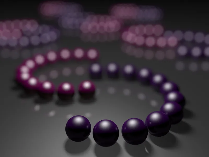
We now reduce the depth of field slightly by only changing the size of the Blender to 0.4. We leave all other parameters as they are.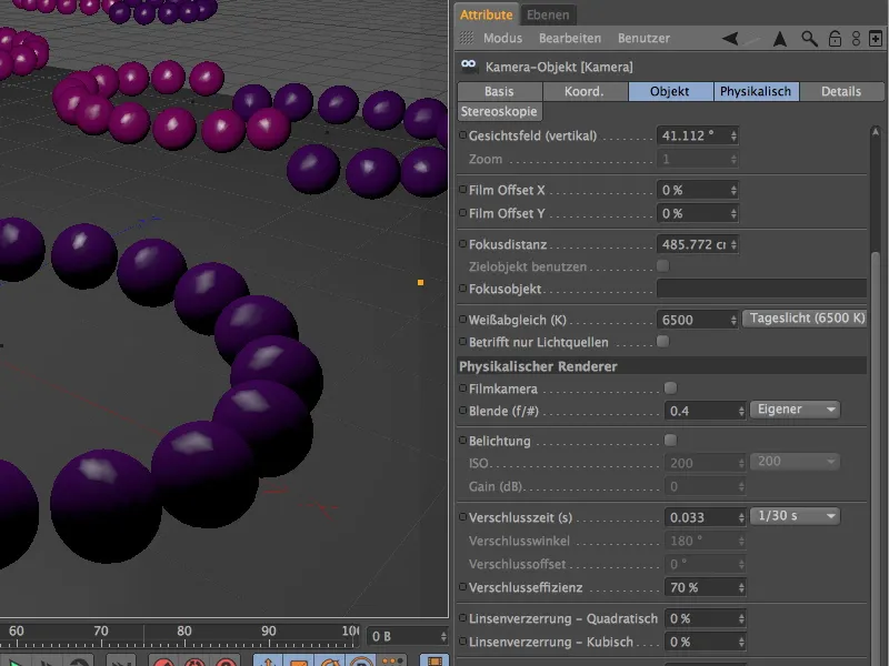
Now the rearmost spheres can be recognized as such again. The depth of field remains the same, of course, as we have only reduced the strength of the depth of field by modifying the aperture.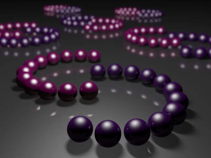
Varying the aperture shape
We set the aperture back to the stronger value so that we can take a better look at the shape of the aperture in the next example. Thanks to the physical camera, we can not only work with other parameters, but can also modify these rather design-specific parameters.
In the settings dialog on the Physical page, after activating the Aperture shape option, you will find additional parameters to implement other or custom aperture shapes. While the default setting uses a round Blender shape, we can also simulate lamellar Blenders by specifying a number of lamellas.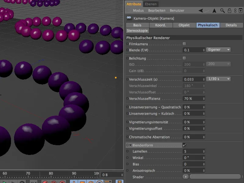
Now it becomes clear why I have placed so much emphasis on as many highlights as possible in this example scene. As the blur increases, the highlights visibly take on the shape of the aperture - thanks to the shape of the aperture with five blades as a pentagon.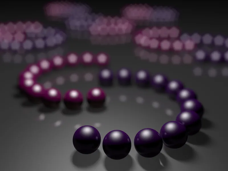
As far as the aperture shape is concerned, we are not limited to the standard aperture and the variable blades. We can also define suitable textures or shaders as aperture shapes via the shader menu in the arrow button.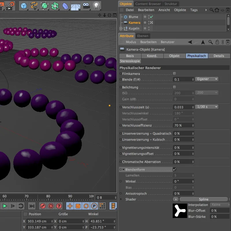
For the next example, I have created a Blum spline within a spline shader as a shader. Thanks to the white fill and black background, I can now easily use this spline-based shape as an aperture.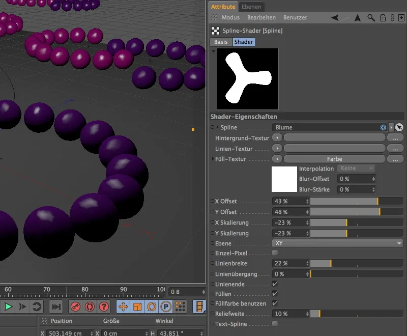
As this particular aperture shape also places higher demands on the sample quality, I increased the subdivisions slightly in the render presets.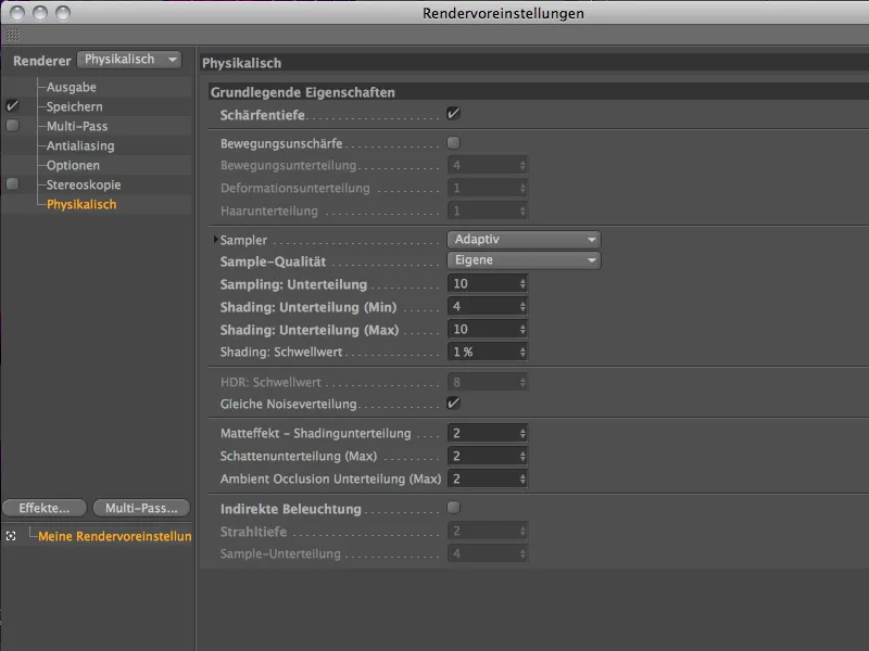
With these settings, after another time-consuming rendering process, the shader with the three-leaf Blum spline appears as an aperture shape in the blurred highlights.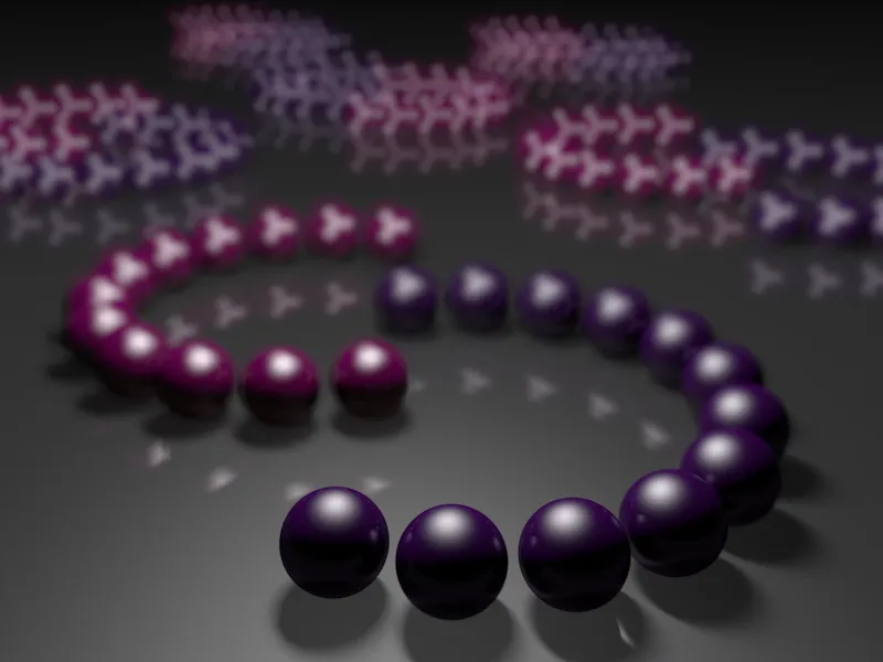
Vignetting effect
With the vignetting effect, the physical camera offers a way of darkening the edges of the image using a radial, soft gradient. It is, so to speak, a simulation of the design limitations of a camera in which not all rays of light enter the aperture at the required angle.
For this example, I created a second physical camera with a lamellar aperture shape, all other parameters are identical with the exception of the slightly enlarged aperture. To make the vignetting effect as visible as possible, we set a value of 200% for the vignetting intensity, the corresponding vignetting offset of 40% causes a narrowing of the visible, non-darkened image section.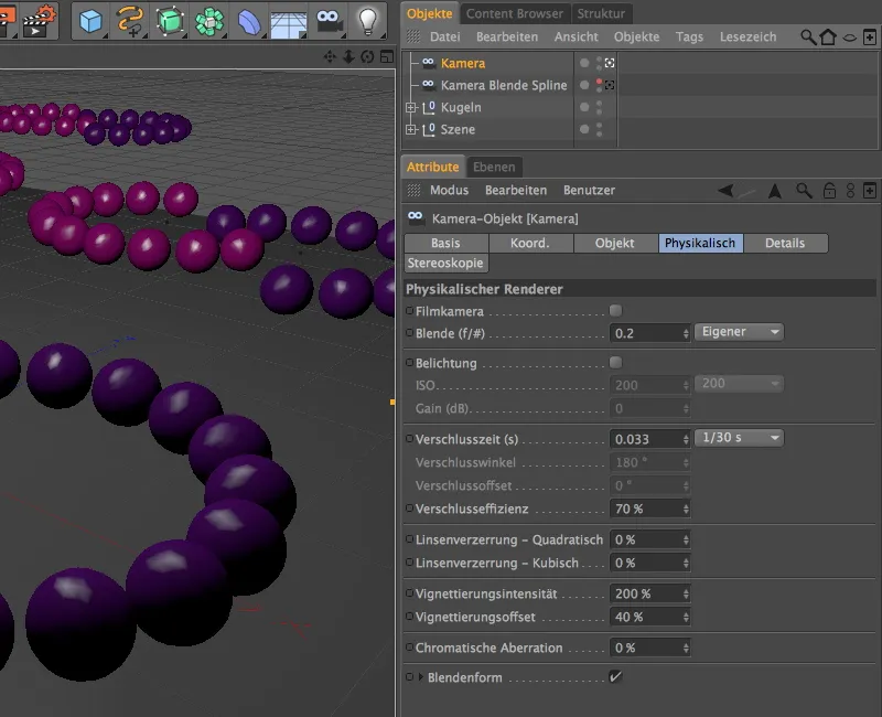
As you can see, this vignetting effect can also be used to successfully reduce areas of the image that are too dominant and over-illuminated by many highlights.